
Table of contents: Cylinder head cover ↓ Cylinder head ↓
1. The details of the cylinder head and its cover installation are shown in the illustration.
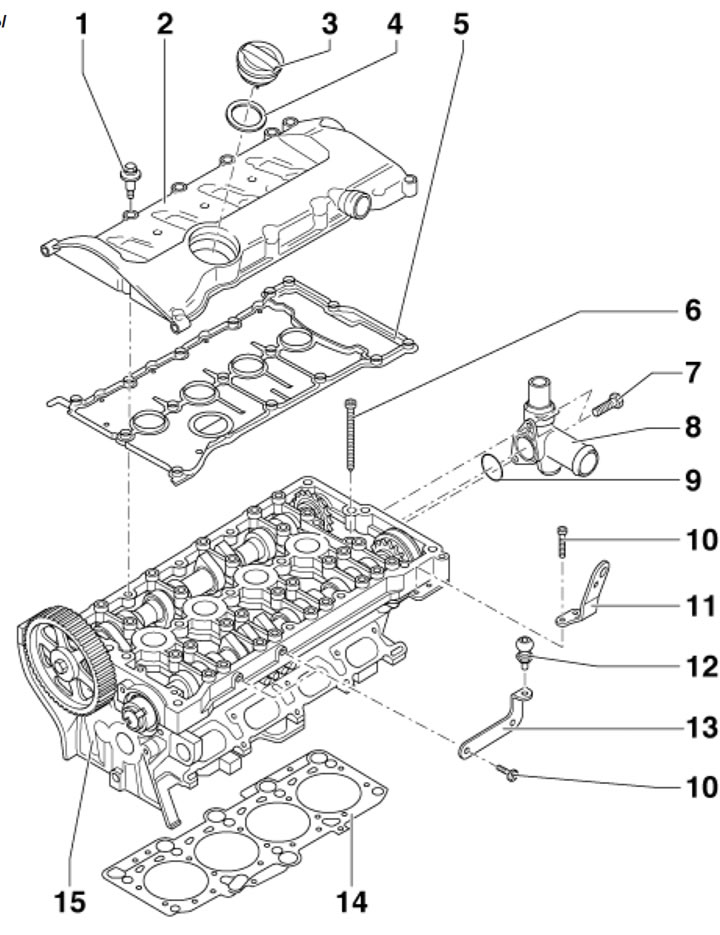
13.1. Cylinder head and cover installation details 1. Special cover mounting bolts 2, 10 Nm; 2. Cylinder head cover; 3. Oil filler cap; 4. Cover sealing ring 3; 5. Cover gasket 2; 6. Cylinder head cover mounting bolts; 7. Pipe mounting bolts 8, 10 Nm; 8. Connecting pipe; 9. Sealing ring of branch pipe 8; 10. Bolts for fastening eye 11 and bracket 13, 10 Nm; 11. Engine lifting eye; 12. Bolt for upper engine cover; 13. Bracket; 14. Cylinder head gasket; 15. Cylinder head
Cylinder head cover
2. Remove the decorative (upper) engine cover upwards (see illustration 5.21).
3. If there is a casing (1 in illustration 5.11) on the right side of the engine compartment, remove this cover.
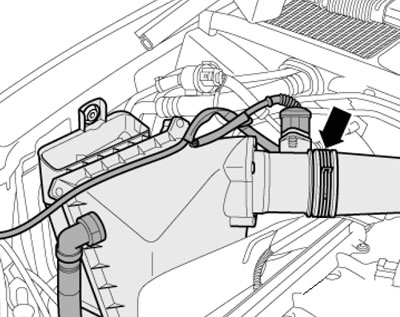
4. Disconnect the EVAP valve solenoid connector (1 in illustration 5.12) and remove the electromagnetic valve. Unscrew the screws (arrows) and remove the air duct (2).
5. Remove the bolts (5 in illustration 10.1) and remove the upper timing belt cover.
6. Disconnect the air duct (arrow on the illustration) from the air purifier.
13.6. Connecting the air duct to the air purifier
7. Disconnect the air ducts (1 and 2 in Illustration 5.28), as well as the hose on the underside of the duct. Remove the duct.
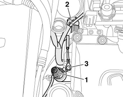
8. Remove the bolts (1 in the illustration), disconnect the ignition coil connectors (2) and release the cable channel.
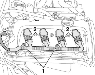
13.8. Ignition coil wiring bolts and connectors
9. Remove the hose (1 in the illustration) PCV on the cylinder head cover and remove the ignition coils (2) upwards.
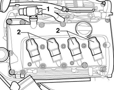
13.9. PCV hose (1) and ignition coils (2)
10. Remove the cylinder head cover mounting bolts in the following sequence: (16-1 in the illustration) and take it off.
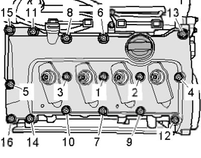
13.10. Cylinder head cover fastener tightening sequence
11. Installation is performed in the reverse order of dismantling the components. Please note the following features.
12. A damaged cylinder head cover gasket and bolts with damaged gaskets must be replaced.
13. Tighten the cylinder head cover mounting bolts in the following sequence: (1-16 in illustration 13.10).
Cylinder head
14. Disconnect the negative cable from the battery.
15. Drain the coolant from the cooling system.
16. Install the radiator frame in the service position (see Section 6).
17. Loosen the clamping sleeve nuts and move the exhaust pipe mounting clamp back (see illustration 5.42).
18. Remove the exhaust pipe bracket nut (see illustration 5.41).
Note: The flexible section of the intake pipe must not be bent more than 10°, otherwise it may be damaged.
19. Disconnect the air ducts (1 and 2 in Illustration 5.28), as well as a hose on the underside of the duct.
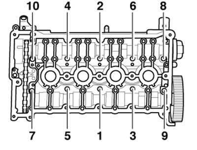
20. Disconnect the connector (1 in illustration 5.29) air flow meter, remove the hose (2, if available) and remove the air cleaner housing by removing the spring clip (3).
21. Remove the catalytic converter fasteners from the exhaust manifold (see illustration 5.40). Disconnect the catalytic converter from the exhaust manifold.
22. Remove the upper cooling system pipe (see Chapter 3).
23. Remove the intake manifold (see Chapter 4).
24. Disconnect the connector (1 in the illustration) eCT sensor and connector (2) of valve #1 for adjusting the timing phases. Disconnect the ground wire (3), put the wiring harness aside.
13.24. Cylinder head wiring
25. Remove the rear coolant hose from the cylinder head (see Chapter 3).
26. Remove the timing belt from the camshaft sprocket (see Section 10).
27. Perform the actions described in paragraphs 8-10.
28. Remove the cylinder head mounting bolts in the following sequence: (1-10 in the illustration) and remove it with the help of an assistant. The installation procedure is described below.
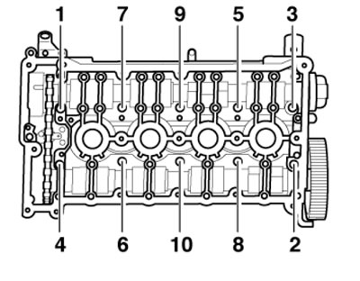
13.28. Sequence of unscrewing the cylinder head mounting bolts
29. Set the camshaft to the TDC position and make sure that the mark on the crankshaft pulley also matches the TDC mark (see illustration 10.15). If necessary, turn the crankshaft.
30. Inspect the cylinder head. If there are small cracks on it, (width up to 0.3 mm) between the valve seats or between the valve seat ring and the spark plug socket thread (no further than the first four thread turns), then the cylinder head can be used without reducing its service life.
31. Prepare new cylinder head mounting bolts, new self-locking nuts and bolts, new angle-tightening bolts, as well as new sealing rings, cuffs and gaskets.
32. Carefully remove any remaining sealant from the cylinder head and cylinder block, avoiding the formation of long scratches or burrs. Carefully remove any remaining sandpaper or grinding material. There should be no oil or coolant in the blind threaded holes of the cylinder head.
33. When installing a new cylinder head with the camshafts installed, the mating surfaces between the hydraulic compensators and the camshaft cover should be lubricated with engine oil after installing the head. The plastic linings included in the repair kit for protecting open valves may be removed immediately before installing the cylinder head.
34. The new cylinder head gasket should be removed from the packaging immediately before installation. The gasket should be handled with extreme care. Damage to the silicone layer and corrugated connections will result in loss of sealing.
35. When replacing the cylinder head or its gasket, drain the old coolant and fill it with new coolant.
36. Place the cylinder head gasket on the centering pins in the cylinder block (the gasket number must be read from the inlet side).
37. Place the cylinder head on the cylinder block and screw in all the new bolts by hand. Then tighten the cylinder head bolts in three steps in the sequence (1-10 in the illustration), at the first stage - with a force of 40 Nm, and at the second and third stages - tighten the bolts each time at an angle of 90°.
13.37. Sequence of tightening the cylinder head bolts
38. Further installation is carried out in the reverse order of dismantling the components.