



Table of contents: Replacing the exhaust shaft seal ↓ Replacing the intake shaft seal ↓ Camshafts and chain tensioner ↓
1. The valve drive mechanism parts are shown in the illustration.
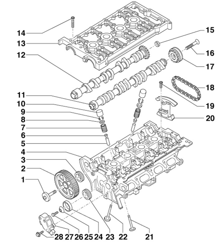
14.1. Timing belt parts 1. Gear wheel mounting bolt 2, 65 Nm; 2. Shaft gear 12; 3. Shaft seal 12; 4. Cylinder head; 5. Valve guide bushing; 6. Oil deflector cap; 7. Valve spring; 8. Upper spring plate 7; 9. Split valve lock crackers; 10. Hydraulic valve clearance compensator; 11. Intake camshaft; 12. Exhaust camshaft; 13. Camshaft cover; 14. Cover mounting bolts 13.8 Nm; 15. Shaft cover 12; 16. Sprocket mounting bolt 17, 100 Nm; 17. Sprocket shaft 11c intake valve phase adjuster; 18. Shaft drive chain 11; 19. Tensioner mounting bolt 20; 20. Hydraulic chain tensioner 18; 21. Exhaust valve; 22. Inlet valve; 23. Shaft seal 11; 24. Plug of the CMP sensor; 25. Washer with cone; 26. Oil seal mounting bolt 23, 25 Nm; 27. SMR sensor housing; 28. Housing mounting bolt 27, 10 Nm
Replacing the exhaust shaft seal
2. Install the radiator frame in the service position (see Section 6).
3. Remove the timing belt from the camshaft sprocket (see Section 10).
4. Holding the camshaft gear from turning with tool #3306, unscrew the central bolt and remove the gear (see illustration).
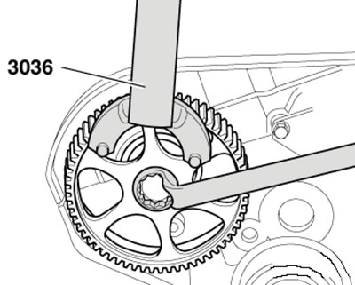
14.4. Removing/installing the camshaft gear
5. Screw the gear mounting bolt into the camshaft by hand, install the inner part of the seal puller #2085 flush with the outer part and secure with a knurled head bolt. Lubricate the threaded head of the puller with engine oil, install and, pressing hard, screw it as deep as possible into the seal (see illustration). Loosen the knurled bolt and rotate the inner part against the camshaft until the seal is removed. Clamp the flats of the removed puller in a vice and remove the seal with pliers.
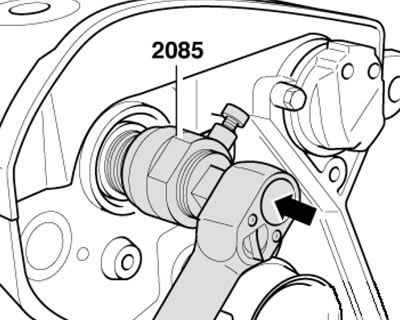
14.5. Removing the exhaust camshaft oil seal
6. Place guide sleeve No. T10071/1 on the camshaft journal (see illustration). Without lubricating the working edge of the seal, place it through the guide sleeve onto the shaft journal, then remove the guide sleeve.
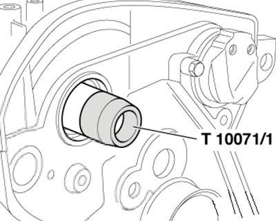
14.6. Guide bushing
7. Press the oil seal using sleeve No. T10071/3 and bolt No. T10071/4 until it stops (see illustration).
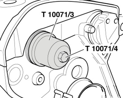
14.7. Pressing in the oil seal
8. Install the camshaft gear so that the narrow web of the gear faces outward (arrows in the illustration), and the TDC mark of cylinder No.1 was visible.
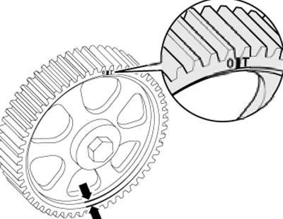
14.8. Installation position of the gear wheel
9. While holding the gear wheel from turning, tighten its mounting bolt.
Caution: When turning the camshaft with the timing belt removed, none of the pistons should be at TDC.
10. Install the timing belt (see Section 10).
11. Further installation is carried out in the reverse order of dismantling the components.
Replacing the intake shaft seal
12. Remove the decorative (upper) engine cover upwards (see illustration 5.21).
13. If there is a casing (1 in illustration 5.11) on the right side of the engine compartment, remove this cover.
14. Disconnect the EVAP valve solenoid connector (1 in illustration 5.12) and remove the solenoid valve. Unscrew the screws (arrows) and remove the air duct (2).
15. Disconnect the CMP sensor connector (see illustration).
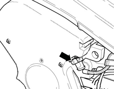
14.15. SMR sensor connector
16. Remove the bolts (5 in illustration 10.1) and remove the upper timing belt cover.
17. Remove the CMP sensor housing, as well as the CMP sensor washers and pads.
18. To insert the seal puller, screw in bolt No.2085/1 (see illustration) into the camshaft by hand until it stops. Unscrew the inner part of the seal puller No.2085 by two turns (by about 3 mm) from the outer part and secure with a knurled bolt.
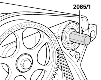
14.18. Bolt for oil seal puller
19. Lubricate the threaded head of puller #2085 with engine oil, install and, pressing hard, screw it as deep as possible into the seal (by analogy with illustration 14.5). Loosen the knurled bolt and turn the inside against the camshaft until the seal is removed. Clamp the flats of the removed puller in a vice and remove the seal with pliers.
20. Place guide sleeve No. T10071/5 on the camshaft journal (by analogy with illustration 14.6). Without lubricating the working edge of the seal, place it through the guide sleeve onto the shaft journal, then remove the guide sleeve.
21. Press the oil seal using sleeve No. T10071/3 and bolt M8x60 until it stops (by analogy with illustration 14.7).
22. Further installation is carried out in the reverse order of dismantling the components.
Camshafts and chain tensioner
Note: The lower seating surface of the camshaft cover and the upper surface of the cylinder head may only be cleaned, and may not be processed. The camshaft bearings are built into the cylinder head and the upper camshaft cover.
23. Set the radiator frame to the service position (see Section 6).
24. Remove the timing belt from the camshaft sprocket (see Section 10).
25. Remove the cylinder head cover (see Section 13).
26. Turn the crankshaft by the pinion bolt at an angle of approximately 45° counterclockwise so that none of the pistons is at TDC.
27. Holding the camshaft gear from turning with tool #3306, unscrew the central bolt and remove the gear (see illustration 14.4).
28. Disconnect the CMP sensor connector (see illustration 14.15). Remove the CMP sensor housing, as well as the CMP sensor washers and pads.
29. Disconnect the connector (2 in illustration 13.24) valve No.1 of the timing phase adjustment and disconnect the ground wire (3). Do not disconnect the ECT sensor connector (1).
30. Remove the bolts (see illustration) and remove the valve No.1 for adjusting the timing phases with the distribution mechanism cover.
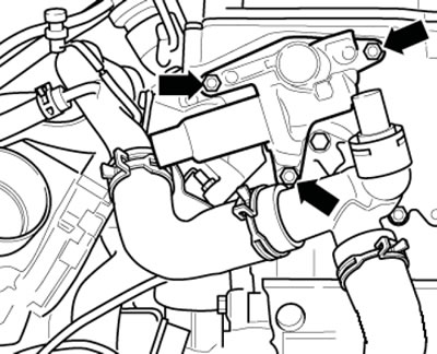
14.30. Timing phase adjustment valve mounting bolts
Note: The illustration shows this operation from the rear with the engine removed.
31. Remove the bolts (1 in the illustration) and remove the heat shield with an upward movement.
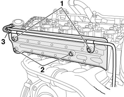
14.31. Fastening the heat shield
32. Check the TDC position of the camshafts again: both marks on the shafts should be opposite both arrows on the camshaft cover (see illustration 14.32a).
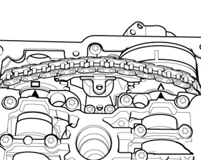
14.32a. TDC marks for camshafts
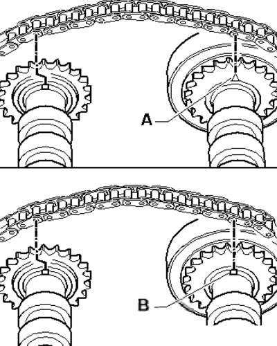
14.32b. Variants of TDC marks on camshafts
Note: Depending on the version, the arrow (And in illustration 14.32b) or the groove (B) may be located on the intake camshaft.
33. If the removed intake camshaft drive chain is intended to be reused, clean it and the camshaft sprockets in the areas opposite both TDC arrows and mark the installation position of the chain relative to the sprockets with a felt-tip pen (see illustration). The distance between the two marks corresponds to 16 chain rollers. The notch on the outlet shaft is offset inward relative to the chain roller (1).
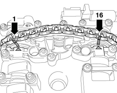
14.33. Chain timing marks
34. Secure the hydraulic chain tensioner using screw No. T10092 and nut M5 (1 in the illustration).
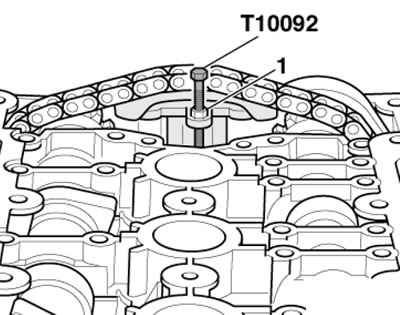
14.34. Fixing the chain tensioner
Note: Overtightening the chain tensioner bracket may damage the tensioner.
35. Unscrew the camshaft cover mounting bolts in the sequence shown in the illustration from outside to inside.
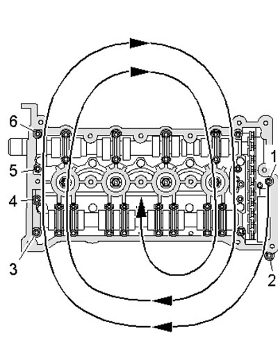
14.35. Sequence of unscrewing the fasteners of the camshaft cover
36. Carefully pry off the camshaft cover by screwing in two bolts MB (see illustration), and take it off.
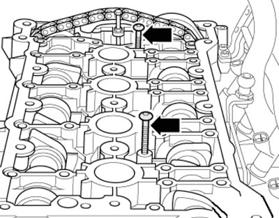
14.36. Separating the camshaft cover from the cylinder head
37. Remove the hydraulic chain tensioner bolts. Carefully, with the hydraulic chain tensioner facing up, remove the camshaft and place it on a clean surface. The installation process is described below.
38. Prepare new gaskets and seals. Make sure the pistons are at TDC.
39. Without allowing dirt and sealant to enter the cylinder head, remove any remaining sealant on the camshaft cover and cylinder head (for example, using a drill with a rotating plastic brush). Clean the mounting surfaces - they should be free of oil and grease.
40. Place the intake shaft drive chain on the sprockets of both shafts. If using the old chain, place it in accordance with the marks made during removal (see illustration 14.33).
41. If a new chain is installed, cams (And in illustration 14.41a) for cylinder No.1 should be located opposite each other. In this case, the distance between the marks (A and B in Illustration 14.41b)on the camshafts there should be 16 chain rollers (the illustration shows where rollers 1 and 16 should be installed on the sprockets; mark (A) relative to the chain roller (1) is shifted inward).
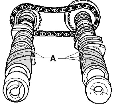
14.41a. Mutual position of cams when installing the chain
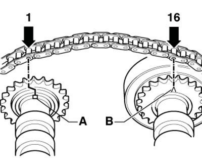
14.41b. Position of the chain relative to the camshafts
Note: Depending on the version, the arrow (1 in illustration 14.32b) or the groove (B) may be located on the intake camshaft.
42. With the help of an assistant, insert the hydraulic chain tensioner between the chain and insert the camshafts with the chain and its tensioner into the cylinder head. Lubricate the camshaft grooves with engine oil.
43. Make sure that the guide bushings of the camshaft mounting frame and the hydraulic chain tensioner are inserted into the cylinder head. Screw on the hydraulic chain tensioner, checking the position of the guide bushings.
44. Apply a 2-3 mm diameter bead of sealant to the clean sealing surface of the lower part of the camshaft cover as shown in the illustration.
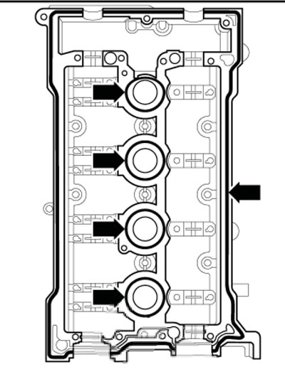
14.44. Places of sealant application
45. Install the camshaft cover onto the cylinder head and secure it with locking pin No. T40029.
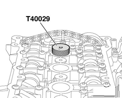
14.45. Fixing the camshaft cover
Note: Install and tighten the camshaft cover without interruption, as the sealing surfaces begin to harden immediately after contact. After installing the cover, allow the sealant to dry for approximately 30 minutes.
46. Tighten the camshaft cover fasteners evenly from the inside out in the sequence shown in the illustration.
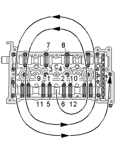
14.46. Sequence of tightening the camshaft cover fasteners
47. Remove locking pin No. T40029 from the camshaft cover using puller No. T10055, remove screw No. T10092 from the timing chain tensioner (see illustration 14.34).
48. Check the correct adjustment of the camshafts: both marks on the shafts should be opposite both arrows on the shaft cover (see illustration 14.32a). To ensure that both marks match, you should, if necessary, move the shafts slightly in one direction or another.
Note: Depending on the version, the arrow (1 in illustration 14.32b) or the groove (B) may be located on the intake camshaft.
49. Install the camshaft seals (see relevant subsections above) and the cover behind the exhaust camshaft.
50. Install valve No.1 of the timing phase adjustment system with a new gasket, having first moistened the valve piston with engine oil.
51. Install the camshaft gear so that the narrow web of the gear faces outward (arrows in illustration 14.8), and the TDC mark of cylinder No.1 was visible.
52. While holding the gear wheel from turning, tighten its mounting bolt.
Caution: When turning the camshaft with the timing belt removed, none of the pistons should be at TDC.
53. Install the CMP sensor and cylinder head cover (see Section 13).
54. Turn the crankshaft by the bolt of its pulley at an angle of approximately 45° clockwise to set the pistons to TDC.
55. Further installation is carried out in the reverse order of dismantling the components.
56. After installing the camshafts, the engine must not be started for approximately 30 minutes. The hydraulic compensators must be settled (otherwise the valves will touch the pistons). After working on the valve train, turn the crankshaft by hand at least two revolutions to ensure that no valve is in contact with the piston.