
Table of contents: Checking hydraulic compensators ↓ Valve seat machining ↓ Checking the valve guides ↓
Attention: It is prohibited to modify the intake and exhaust valves; only lapping is allowed.
1. To replace the valve stem seals, special tools are used to squeeze out the valve spring and remove the valve lock crackers (see illustration 14.1). If the procedure is performed with the cylinder head installed, supply compressed air at a pressure of at least 6 bar to the combustion chamber through the spark plug hole.
Checking hydraulic compensators
Note: Hydraulic tappets cannot be repaired;irregular valve knocking when starting the engine is normal.
2. Start the engine and wait until the radiator fan turns on at least once. Increase the speed for 2 minutes to 2500 rpm, if necessary, conduct a test drive. If the irregular valve knocking disappears, but reappears when driving short distances, then it is necessary to replace the oil filter bracket (see Section 16). If the hydraulic lifters are still noisy, determine the faulty component as follows.
3. Remove the cylinder head cover (see Section 13).
4. Turn the crankshaft so that the cam of the hydraulic compensator being tested is on top: on models with a manual transmission, with 4th gear engaged and the ignition off, move the car forward, and on models with a CVT, remove the soundproofing casing and turn the crankshaft clockwise by the central bolt of the crankshaft pulley.
5. To determine the clearance between the cam and the hydraulic compensator, press it down with a wooden or plastic object. If a 0.20 mm thick feeler gauge fits between the camshaft and the hydraulic compensator, replace the hydraulic compensator (see "Removing the Camshaft" in Section 14).
Note: After installing the camshafts, the engine must not be started for approximately 30 minutes - the hydraulic lifters must be settled, otherwise the valves will come into contact with the pistons.
6. After working on the valve mechanism, turn the engine crankshaft by hand at least two revolutions to make sure that no valve is in contact with the piston.
Valve seat machining
7. If grinding does not achieve perfection of the valve seat working surface, it should be reworked.
8. When repairing engines (especially with a long service life) with leaky valves, it is not enough to treat or replace the valve seats and valves - it is necessary to check the valve guides for wear (see subsection below).
9. Valve seats should be machined only to the extent necessary to achieve a flawless working surface. Before machining, the maximum allowance for machining should be calculated as described below.
Note: If the machining allowance is exceeded, the hydraulic valve clearance adjustment function may be impaired, which will require replacement of the cylinder head.
10. Insert the valve, press it firmly against the seat and measure the distance (and in the illustration) between the end of the valve stem and the top edge of the cylinder head using a depth gauge.
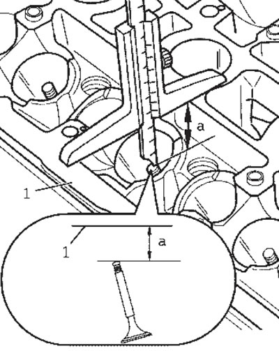
15.10. Measuring the distance between the end of the valve and the cylinder head
Note: If the valve is replaced during repair, a new valve should be used for measurements.
11. Calculate the maximum allowable rework allowance as the difference between the measured distance and the minimum dimension. For outer/middle intake valves, the minimum dimension is 31.0/32.2 mm, and for exhaust valves, it is 31.9 mm.
12. If the maximum allowable machining allowance is 0 mm or less than 0 mm, repeat the measurement with a new valve. If the result is still 0 mm or less than 0 mm, replace the cylinder head. The machining parameters for valve seats are shown in the illustration.
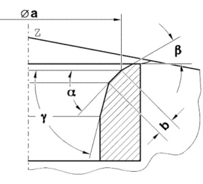
15.12. Processing of the inlet/outlet valve seat a. 26.2/29.0 mm; b. 1.5 + 1.8/1.8 mm; Z. Lower edge of cylinder head; α. 45°(valve seat chamfer angle); β. 30°(angle of the upper correction chamfer); y. 60° (angle of the lower correction chamfer)
Checking the valve guides
13. To check the valve guides, insert the valve into the guide (do not confuse the intake and exhaust valves), so that the end of the valve stem is covered by the guide sleeve.
Note: If the valve is replaced during repair, a new valve should be used for measurements.
14. Determine the valve rocking clearance using a plunger-type dial indicator: the wear limit of the intake and exhaust valve bushings is 0.8 mm.
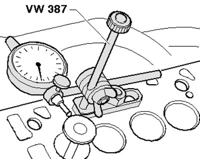
15.14. Determining the valve clearance in the guide
15. If the permissible value is exceeded, repeat the measurement with new valves. If the maximum tolerance is also exceeded with new valves, the cylinder head must be replaced. Valve guides cannot be replaced.