
Table of contents: Engine 1.9-I-TDI-110 hp. ↓ Engine 1.9-I-TDI-115/130 hp. ↓
Engine 1.9-I-TDI-110 hp.
All operations for removing and installing a timing belt on a diesel engine (1.9-I-TDI-110 hp) similar to the operations for removing and installing the timing belt on 1.8-I petrol engines (125/150 hp). The remainder of this section contains operations that are specific to 1.9-I-TDI (110 hp) engines only.
Remove the poly V-belt.
Remove the upper timing belt cover.
Turn the engine crankshaft to the position where the piston of the first cylinder is set to TDC.
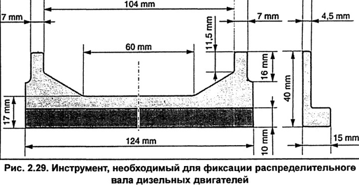
To lock the camshaft in the TDC position of the piston of the first cylinder in the compression stroke, it is necessary to use a special adjustment ruler 2065-A or a tool made independently according to the dimensions shown in Figure 2.29.
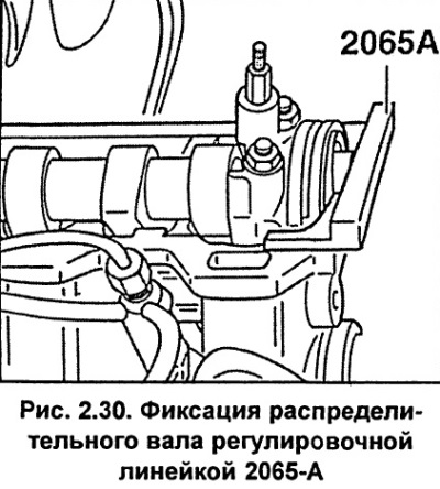
Install the locking tool into the groove in the end of the camshaft (see fig. 2.30).
With the adjustment ruler installed in the camshaft, turn the camshaft (turning the crankshaft clockwise) so that one side of the adjusting ruler is pressed against the surface of the cylinder head. Using the blade of the feeler gauge, measure the gap between the other end of the adjusting ruler and the cylinder head. Turn the camshaft slightly back and install two feeler gauges of a thickness equal to half the previously measured gap on both sides between the adjusting ruler and the cylinder head.
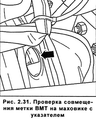
Through the hole in the clutch housing, check that the TDC mark on the flywheel is aligned with the pointer (see fig. 2.31).
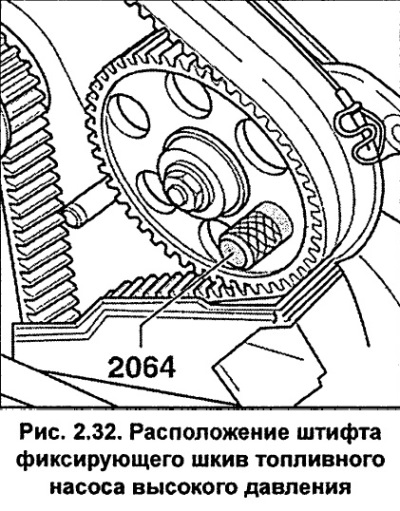
Insert the AUDI-2064 locking pin through the mounting hole of the high pressure fuel pump pulley into the hole in the bracket behind the fuel pump pulley (see fig. 2.32). Instead of the locking pin, you can use a drill shank with a diameter of 15 mm and a length of 36 mm.
Unscrew the guide roller.
Remove the crankshaft pulley and the lower timing belt cover in the same way as for the 1.8-I engine.
Release the tension roller, loosen the tension and remove the timing belt. To reinstall the timing belt, mark its direction of rotation.
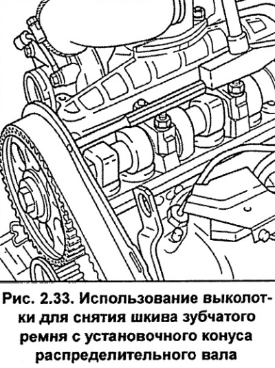
Loosen the camshaft pulley mounting bolt by half a turn, while using the second wrench to hold the camshaft from turning. Remove the timing belt pulley from the camshaft mounting cone using a drift passed through the hole in the rear timing belt cover (see fig. 2.33).
Remove the bolt completely and remove the timing belt pulley from the camshaft.
Install the timing belt guide roller and secure it with the bolt, tightening it to a torque of 25 Nm.
Install the timing belt on the crankshaft pulleys, fuel pump pulley, camshaft pulley and lastly on the tensioner pulley.
Install the pulley with the toothed belt on it onto the camshaft, allowing the pulley to rotate on the shaft.
Remove the high pressure fuel pump locking pin.
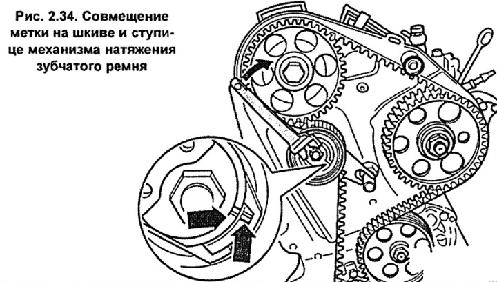
With a wrench (for example, HAZET 2587) turn the timing belt tensioner clockwise until the marks on the pulley and the tensioner hub are aligned (see fig. 2.34).
Tighten the tension roller mounting nut to 20 Nm.
Check again that the TDC mark on the flywheel is aligned with the pointer.
Tighten the camshaft pulley mounting bolt to a torque of 45 Nm, while using the second wrench to hold the camshaft from turning.
Remove the adjusting ruler from the camshaft groove.
Remove the high pressure fuel pump locking pin.
Rotate the engine crankshaft two revolutions in the normal direction of rotation and re-set the piston of the first cylinder to TDC in the compression stroke. Check that the marks on the pulley and the hub of the tensioner mechanism are aligned (see fig. 2.34). Check and, if necessary, readjust the timing belt tension.
Install the timing belt cover, belt pulley (vibration damper), tension roller of the poly V-belt and the cylinder head cover.
Install the poly V-belt.
Check the injection timing of the high pressure fuel pump.
Engine 1.9-I-TDI-115/130 hp.
This section contains only operations related to the 115/130 hp engine. Operations related to all engines are given in the section describing the 1.8-I petrol engines (125/150 hp).
Unscrew the two bolts and remove the poly V-belt tensioner mechanism.
Engine 115 hp. Unscrew the cooling system pipes secured to the timing belt cover and move them to the side.
Remove the upper timing belt cover.
Unscrew the solenoid valve and move it to the side.
Turn the engine crankshaft to the position of installing the piston of the first cylinder at TDC, while the groove between the two protrusions on the rear plate of the camshaft pulley should be aligned with the 4Z mark (see fig. 2.35).
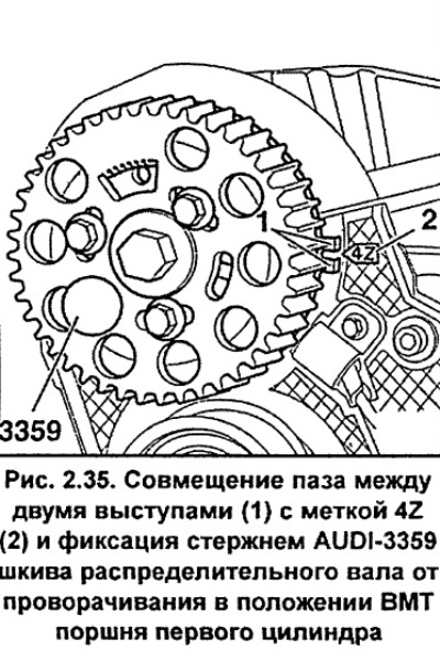
Install the AUDI-3359 locking rod into the hole and secure the camshaft pulley from turning. A 6 mm drill shank can be used instead of the locking rod.
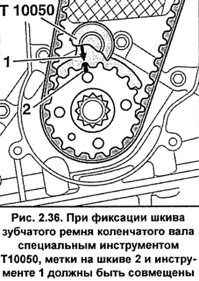
Using special tool T10050, secure the crankshaft timing belt pulley (see fig. 2.36). The marks on pulley 2 (Fig. 2.36) and special tool 1 must be aligned.
Holding the tension roller eccentric with a special key 3387, unscrew the nut by one turn and turn the eccentric clockwise until it stops (see fig. 2.37).
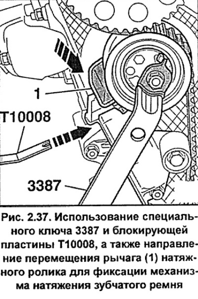
Press down on the tension roller lever 1 (Fig. 2.37) and insert the locking plate T10008, which will secure the timing belt tensioning mechanism.
Using special key 3387, turn the eccentric clockwise until it stops and release the tension roller.
Unscrew the guide roller and remove the timing belt.
Install and screw in the tension roller.
Using special key 3387, turn the tension roller eccentric clockwise until it stops.
Install the timing belt on the camshaft pulley, tensioner roller, crankshaft pulley and water pump pulley.
Turn the tension roller eccentric counterclockwise until it stops and remove the T10008 locking plate.
Adjust the tension of the toothed belt. To do this, use the special key 3387 to turn the eccentric clockwise until a 4 mm drill shank can be inserted between the lever and the housing (see fig. 2.38).
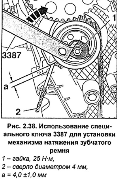
Holding the tension roller in this position, tighten nut 1 (Fig. 2.38) securing the roller to a torque of 25 Nm.
Remove the locating pin 3359 and special tool T10050 that secured the camshaft and crankshaft pulleys.
Turn the engine crankshaft two revolutions in the normal direction of rotation, set the piston of the first cylinder to TDC in the compression stroke and check the dimension a (Fig. 2.38). If the dimension differs from the required one, re-adjust and tighten the tension roller eccentric fastening nut to a torque of 30 Nm.
Install the timing belt cover.
Screw on the crankshaft belt pulley and tighten its mounting bolts to a torque of 10 Nm. Before screwing in the bolts, apply AUDI D000600A2 locking compound to the bolt threads.
Screw on the solenoid valve.
Install and secure the cooling system pipes to the timing belt cover.
Install and screw in the poly V-belt tensioner mechanism.