Table of contents: Timing drive. Petrol engine 1.6 l ALZ ↓ Petrol engines 1.8 and 2.0 l (AVJ,… ↓ Installation (valve timing… ↓ Petrol engine 2.0 l AWA ↓ Installation (valve timing… ↓
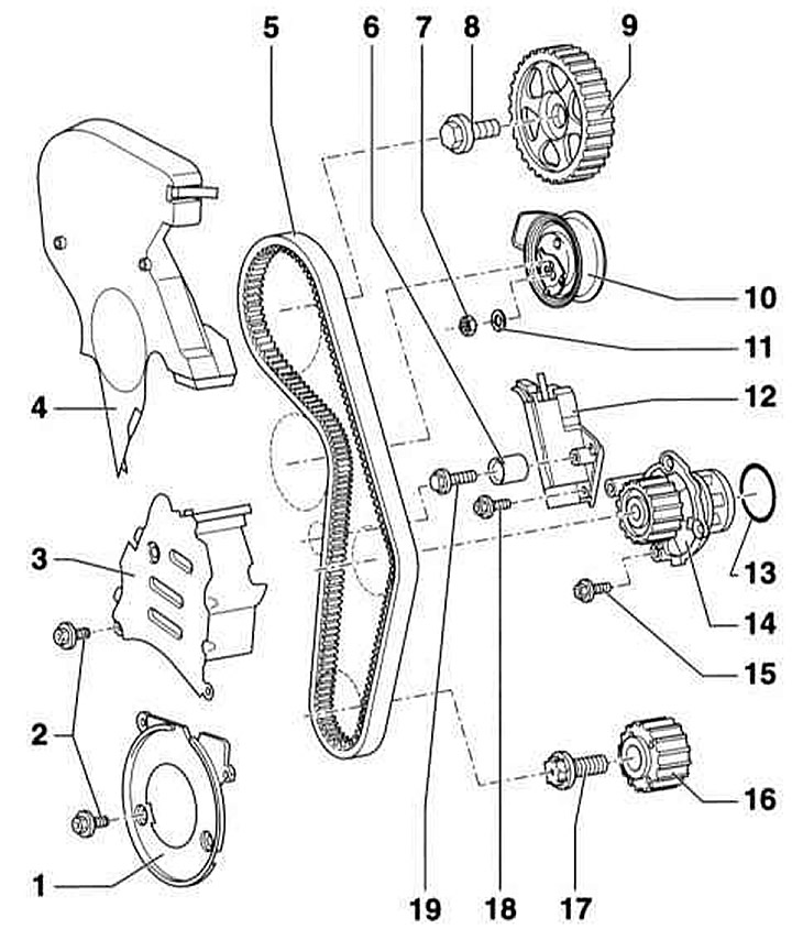
Timing drive. Petrol engine 1.6 l ALZ
- 1 - Twist lock. To open, turn counterclockwise
- 2 - Upper timing belt cover
- 3 - Bolt, 100Nm
- 4 — Timing belt wheel
- 5 - Combination screw, 10Nm
- 6 - Rear timing belt cover
- 7 - Hexagon socket head cap screw, 15Nm
- 8 — O-ring. Be sure to replace. When installing, moisten with G12 coolant
- 9 — Coolant pump
- 10 — Toothed belt. If a used belt is used, mark its direction of rotation with chalk or a felt-tip pen before removing it. Do not bend the belt
- 11 — Crankshaft gear. Attention: There should be no oil on the mating surface between the gear wheel and the crankshaft
- 12 - Bolt, 90Nm + 90°. Be sure to replace. The thread and bearing surface must not have any grease
- 13 — Lower timing belt cover
- 14 - Bolts, 10Nm
- 15 — Crankshaft pulley/vibration damper
- 16 - Screw, 25Nm
- 17 — Timing Belt Center Cover
- 18 — Tension roller
- 19 — Washer
- 20 - Nut, 20Nm
Removal
1. Set the front panel to the service position, refer to Section Setting the front panel to the maintenance position.
2. Remove the top engine cover.
3. Remove the V-belt, refer to Section Removal and installation the accessory drive belt.
4. Disconnect the V-belt tensioner.
Caution: Draw the installation position of the upper timing belt cover, particularly where it transitions to the center cover.
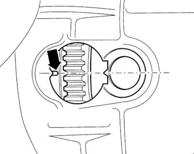
5. Turn the rotary lock counterclockwise (arrow in Fig. A) so that the screw slot is in a vertical position.
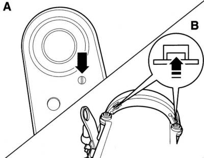
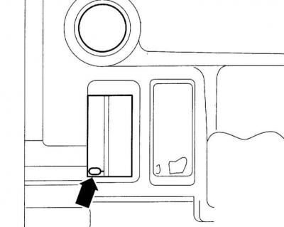
6. Disconnect the upper timing belt cover. To do this, press the locking tabs of the clamp upwards (arrow in Fig. B).
7. Remove the upper timing belt cover.
8. Apply the parking brake and set the transmission to neutral.
9. Set the engine to the TDC of the piston of the first cylinder. To do this, turn the crankshaft by the central bolt of the gear wheel in the direction of engine rotation, i.e. clockwise so that the marks on the camshaft wheel and on the crankshaft coincide.
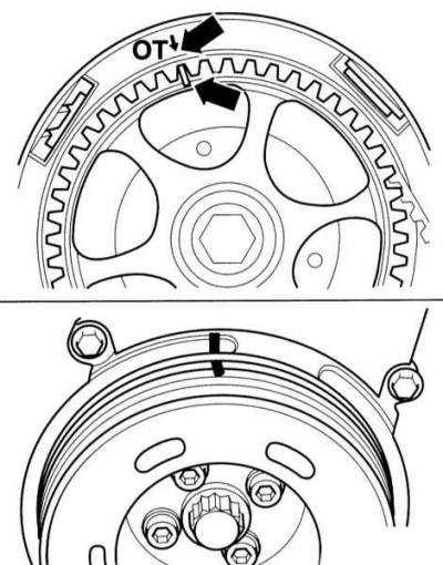
10. Manual transmission: The TDC marks on the flywheel and drive disk must match.
11. AT: The TDC mark should be located at the left edge of the window (arrow on the accompanying illustration).
12. Loosen the crankshaft pulley mounting screws and remove the pulley.
13. Disconnect the center and lower timing belt covers (arrows) and remove them.

14. Use chalk or a felt-tip pen to mark an arrow on the timing belt indicating the direction of rotation.
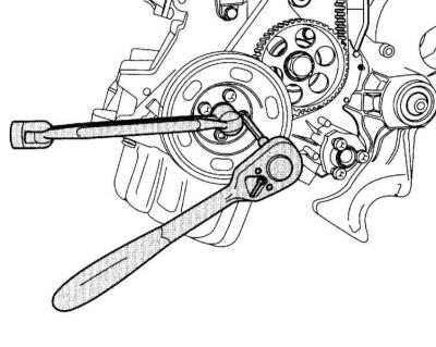
15. Loosen the clamp nut (20) securing the tension roller (18). Turn the tension roller clockwise using tool T10020 and thus loosen the toothed belt tension, see Timing Drive. 1.6 l ALZ Petrol Engine and the accompanying illustration.

16. Remove the timing belt.
Installation (valve timing adjustment)
Caution: If the timing belt is removed from the camshaft wheel only during repairs, valve timing adjustment is required.
When turning the camshaft without a timing belt, do not set any cylinder to the TDC position. There is a risk of damaging the valves and/or piston crowns.
1. Turn the gears so that the marks on the camshaft gear and the rear timing belt cover, as well as the marks on the crankshaft gear and the lower timing belt cover, are aligned. To do this, briefly install the crankshaft gear.
2. Place the timing belt on the crankshaft sprocket.
Caution: Observe the direction of its rotation.
3. Replace the center and lower timing belt covers and secure them.
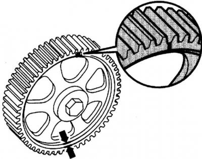
4. Install the crankshaft wheel so that the hole on the wheel matches the protrusion on the crankshaft wheel. In this position, tighten the wheel with torque 25Nm.
5. Place the timing belt on the tension roller and camshaft wheel.
Timing Belt Tension
Caution: The engine must be warmed up to a temperature no higher than hand temperature.
1. Check that the marks on the camshaft wheel and the rear timing belt cover, as well as on the crankshaft wheel and the lower timing belt cover, are aligned.
2. Before tensioning the timing belt, turn the tension roller on the eccentric using the T10020 tool five times in both directions until it stops.
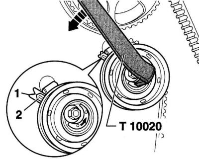
3. Turn the eccentric with the T10020 tool counterclockwise (direction of the arrow in the illustration) all the way.
4. Slowly tighten the timing belt until the mark (1) and pointer (2) are opposite each other. If necessary, use a mirror for checking.
5. While holding the tension roller in this position, tighten the mounting nut to the specified torque 20Nm.
6. Turn the crankshaft two more revolutions in the direction of engine rotation so that the engine stops at TDC of the first cylinder. It is important that the last 45° rotation is performed without stopping.
7. Check the timing belt tension again: The pointer and mark should be opposite each other.
Further installation
1. Secure the upper timing belt cover. Turn the rotary lock clockwise until the screw slot is horizontal.
2. Tighten the V-belt clamping element with torque 25Nm.
3. Put on the V-belt, refer to Section Removal and installation the accessory drive belt.
4. Install the engine top cover, refer to the relevant Section.
5. Set the front panel to the service position, refer to Section Setting the front panel to the maintenance position.
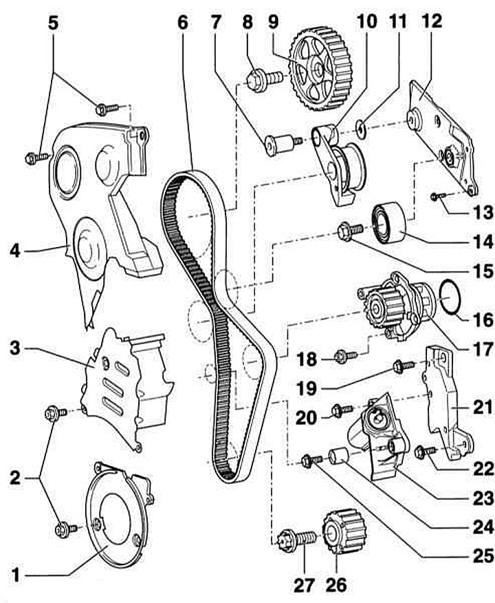
Petrol engines 1.8 and 2.0 l (AVJ, BFB, ALT)
Timing drive. Petrol engines 1.8 and 2.0 l (AVJ, BFB, ALT)
- 1 - Lower timing belt cover
- 2 - Bolt, 10Nm. Screwed in with sealant
- 3 — Central toothed belt cover. To remove, unscrew the V-belt tensioner
- 4 - Upper timing belt cover
- AVJ, BFB engines: When installing, carefully connect with the center cover of the timing belt.
- ALT engine: 10Nm.
- 5 - Toothed belt
- 6 - Guide roller
- 7 — Terminal nut, 27Nm
- 8 - Bolt, 65Nm
- 9 — Exhaust camshaft wheel
- 10 — Tension roller
- 11 — Washer
- 12 — Timing belt tensioner
- 13 — O-ring. Be sure to replace. When installing, moisten with coolant
- 14 — Coolant pump
- 15 - Bolt, 15Nm
- 16 — Crankshaft timing belt wheel. There should be no oil on the mating surface between the timing belt wheel and the crankshaft
- 17 - Bolt, 90Nm + 90°. Be sure to replace. Do not lubricate
- 18 - Bolt, 15Nm
- 19 - Bolt, 25Nm
Position of the camshaft wheel. The narrow wall of the camshaft wheel points outward (arrows), and the TDC mark of the first cylinder is visible from the front
The removal and installation procedures are similar to the 1.6L petrol engine. Therefore, only the differences are described.
Removal
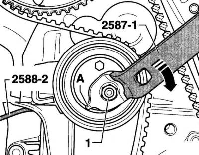
Caution: The tensioner element of the timing belt tensioner (A) is oil-damped and can only be compressed slowly and under uniform load. Excessive compression force may damage the tension roller.
1. Insert the socket wrench into the hex hole of the tension roller until it stops and turn the tension roller counterclockwise (following the arrow on the accompanying illustration) so that the tensioning device can be fixed with HAZET 2588-2 plates.
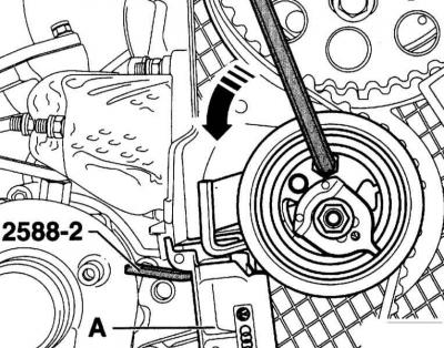
Caution: Turn the tension roller without applying excessive force.
Caution: Insert the socket wrench as far as it will go so that the hex key on the tension roller is not damaged when turning it.
Warning: The timing belt tensioner is oil damped. Press it slowly and evenly.
Caution: Do not bend the eccentric lever stop tab (A).
2. To tension the toothed belt, loosen the nut (1) of the tension roller and turn the eccentric with the HAZET 2587-1 key in the direction of the arrow.
3. If you are installing a previously used toothed belt, mark the direction of rotation on it with chalk or a felt-tip pen.
4. Remove the timing belt.
Installation (valve timing adjustment)
Installation is carried out in the same way as the same procedure for a 1.6 l petrol engine.
Timing Belt Tension
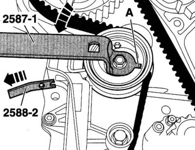
Caution: If the timing belt tensioner is fully extended, it must be rotated back together with the tension roller in the installed position. This process may take up to 5 minutes. Excessive compression force may damage the tension roller.
1. If the timing belt tensioner is fully extended, press the tension roller counterclockwise with a socket wrench until the tensioner piston can be locked by the HAZET 2588-2 locking plates.
Caution: Turn the tension roller evenly without applying too much force.

Caution: Do not bend the stop nose (A) of the eccentric lever.
2. Turn the eccentric with the HAZET key 2587-1 counterclockwise so that the locking plate HAZET 2588-2 can be pulled out.
3. Then turn the eccentric clockwise so that a drill bit of size a = 8 mm can pass between the tension lever and the tensioner body.
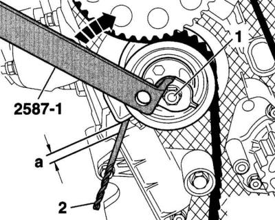
4. While holding the eccentric in this position, tighten the tension roller mounting nut (1). Then remove the nut tightening wrench.
5. Turn the engine two revolutions using the central bolt of the crankshaft (clockwise) and set it back to TDC of the ignition timing.
6. Check the dimension (a) between the tension lever and the tensioner body with a drill. The specified dimension should be 6÷10 mm.
7. If dimension (a) is smaller, loosen the belt, compress the tensioner and re-tighten the timing belt.
8. If the size(s) is reached, complete the installation process.
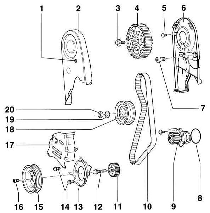
Petrol engine 2.0 l AWA
Timing drive. Petrol engine with direct injection 2.0 l AWA
- 1 - Lower timing belt cover
- 2 - Bolt, 10Nm. Screwed in with fixing agent
- 3 — Central toothed belt cover. To remove, unscrew the V-belt tensioner
- 4 — Upper timing belt cover. When installing, carefully connect it to the center timing belt cover and tighten it with torque 10Nm
- 5 - Bolt, 10Nm
- 6 - Toothed belt
- 7 — Terminal nut, 27Nm
- 8 - Bolt, 65Nm
- 9 — Exhaust camshaft wheel
- 10 — Guide roller holder
- 11 — Washer
- 12 — Tension roller locking plate
- 13 - Bolt, 9Nm
- 14 — Guide roller
- 15 - Bolt, 40Nm
- 16 — O-ring. Be sure to replace. When installing, moisten with coolant
- 17 — Coolant pump
- 18 - Bolt, 15Nm
- 19 - Bolt, 40Nm
- 20 - Bolt, 15Nm
- 21 — Belt tensioner damper locking plate
- 22 - Bolt, 16Nm
- 23 — Belt tensioner damper
- 24 — Guide roller
- 25 - Bolt, 25Nm
- 26 — Crankshaft timing belt wheel. There should be no oil on the mating surface between the timing belt wheel and the crankshaft
- 27 - Bolt, 90Nm + 90°. Be sure to replace. Do not lubricate
Removal
1. Removal and installation are similar to the same procedures for the 1.6L petrol engine. Therefore, only the differences are described here (refer to the illustration above).
2. Loosen the mounting bolts at the top and remove the timing belt cover. Note: To facilitate subsequent installation, mark the position of the transition to the center timing belt cover.

Caution: The tensioner element of the timing belt tensioner (A) is oil-damped and can only be compressed slowly and under uniform load. Excessive compression force may damage the tension roller.
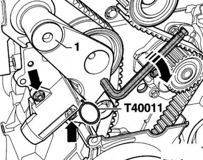
3. Press the tension roller clockwise with a socket wrench (arrow on the accompanying illustration) so that the piston can be secured to the tensioner piston with the appropriate pin, such as T40011.

Caution: Turn the pulley evenly without applying excessive force. If the old timing belt is to be installed, mark the direction of rotation with chalk or a felt-tip pen.
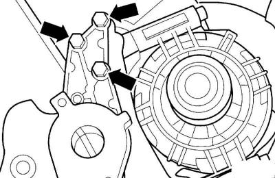
4. Unscrew the holder with the guide roller (1). The arrow indicates the bolts for fastening the belt tensioner damper.
5. Remove the timing belt.
Installation (valve timing adjustment)
Installation is carried out in the same way as the same procedure for a 1.6 l petrol engine.
Finally, install and secure the holder with the guide roller and the spacer washer (11), refer to the illustration Timing drive. Petrol engine with direct injection 2.0 l AWA.
Timing Belt Tension
1. Turn the tension roller clockwise with a socket wrench until the locking pin can be removed.
2. Slowly turn the tension roller counterclockwise with a socket wrench to tighten the timing belt.
Caution: If the timing belt tensioner is fully extended, it must be rotated back together with the tension roller in the installed position. This process may take up to 5 minutes. Excessive compression force may damage the tension roller.
3. If the timing belt tensioner is fully extended, press the tension roller counterclockwise with a socket wrench until the tensioner piston can be locked with the appropriate pin, e.g. T40011.
Caution: Turn the tension roller evenly without applying too much force