
Cylinder block, crankshaft and flywheel of a V6 engine
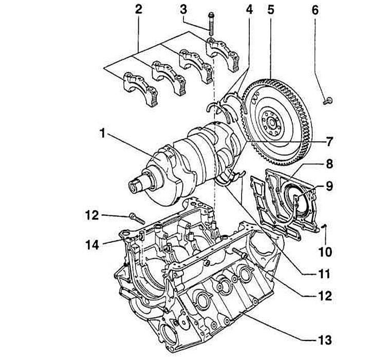
- 1 — Crankshaft
Checking axial play:
- New: 0.07-0.23 mm
- Wear limit: 0.25 mm
- Radial clearance check using Plastigage: 0.018 - 0.045 mm
- Wear limit: 0.10 mm
Attention: When checking the radial clearance, do not rotate the crankshaft.
- 2 — Main bearing cap 4 with recess for thrust washer
- 3 - Bolt. Replace, 60 Nm+90°. To measure the radial clearance, tighten the bolt with a force of no more than 60Nm
- 4 — Main bearing thrust washer 4
- 5 — Flywheel/Drive Disc
- 6 - Flywheel/drive plate bolt. Replace, (flywheel 60Nm+180°), (drive disk 60 Nm+90°). When giving up, use tool 3242 to lock the crankshaft
- 7 — Main bearing shells. Do not mix up the removed shells
- 8 — Sealed flange with seal. Replaced as an assembly. Drain coolant before removing
- 9 — Gasket. Replace
- 10 - Bolt, 10 Nm
- 11 — Cylinder block thrust washer, bearing 4
- 12 - Bolt, 25 Nm. Pre-tighten by hand before tightening the main bearing cap bolts
- 13 — Cylinder block
- 14 — Guide bushing
Main elements of the V6 engine timing drive
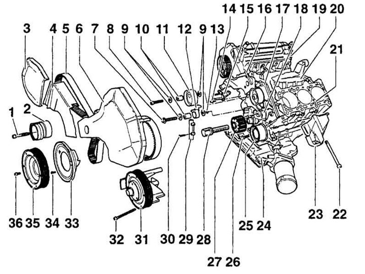
- 1 - Bolt, 55 Nm
- 2 — Timing belt tensioner. Before removing, lock with tool 3204
- 3 - Upper right timing belt cover
- 4 - Center right timing belt cover
- 5 — Toothed belt. Before removing, mark the direction of the belt. Check for wear. Do not bend
- 6 - Upper left timing belt cover
- 7, 8 - Bolt, 25 Nm
- 9 — Washer
- 10 — Bearing bushing
- 11 — Timing belt tension roller
- 12 — Tension lever
- 13 — Sealing ring
- 14 - Bolt, 25 Nm
- 15 — Bracket
- 16 - Connection (thermostat housing)
- 17 - Water pump
- 18 — Oil pump
- 19 — Cylinder head
- 20 — Crankcase breather housing
- 21 — Cylinder block
- 22 - Bolt, 45 Nm
- 23 — Bracket
- 24 — Oil pan
- 25 — Guide roller
- 26 - Bolt, 45 Nm
- 27 — Crankshaft gear
- 28 - Bolt 200 Nm+180°, replace
- 29 — Belt tensioner
- 30 - Bolt, 10 Nm. Install with D6 grease
- 31 — Fan pulley
- 32 — Bolt M8 - 25 Nm, M6 - 10 Nm
- 33 — Timing belt cover
- 34 - Bolt, 10 Nm
- 35 — Torsional vibration damper
- 36 - Bolt, 25 Nm
Chain drive intake camshaft. V6 engine
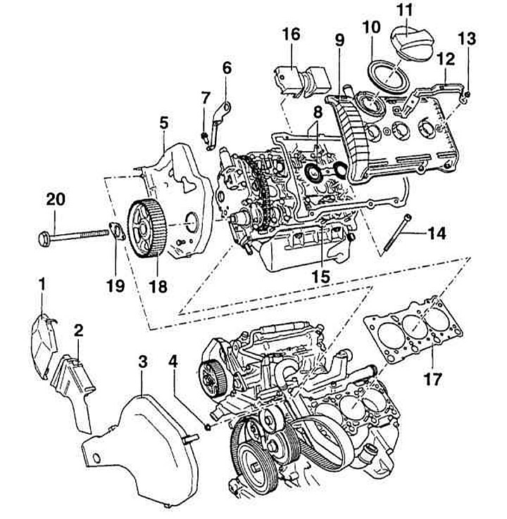
- 1 - Upper right timing belt cover
- 2 - Center right timing belt cover
- 3 - Upper left timing belt cover
- 4 - Hex nut, 10 Nm
- 5 - Rear timing belt cover
- 6 - Lifting eye
- 7 - Bolt, 25 Nm
- 8 — Cylinder head cover gasket. Replace if damaged. Before installation, lubricate the gasket surface between the bearing cover and the cylinder head with D 454 300 A3 grease
- 9 — Cylinder head cover
- 10 — Gasket
- 11 — Cover. If damaged, replace the gasket
- 12 — Bracket
- 13 - Hex nut, 10 Nm. Tighten from the center outward
- 14 — Cylinder head bolt. Replace
- 15 — Cylinder head. Check flatness
- 16 — Oil deflector
- 17 — Cylinder head gasket (metal). Replace
- 18 — Crankshaft gear
- 19 — Clamping plate
- 20 - Bolt, 55 Nm
Cylinder head components. V6 engine
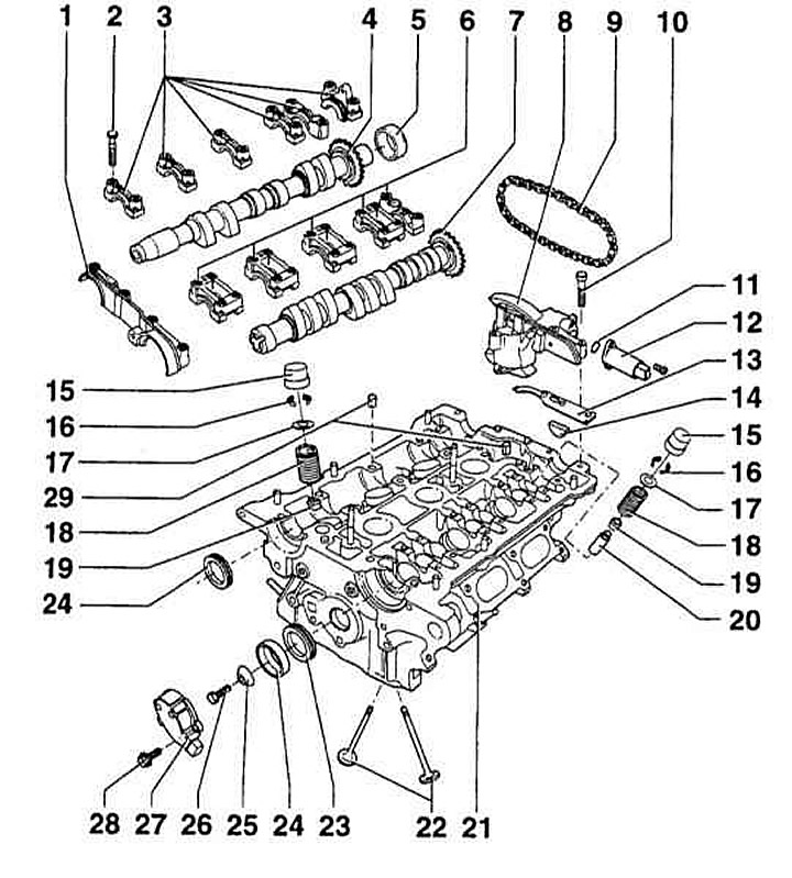
- 1 - Double bearing cap. Lightly lubricate the mating surface with AV 174 004 01 grease
- 2 - Bolt, 10 Nm
- 3 — Camshaft bearing covers for exhaust valves. Lightly lubricate the mating surfaces of the extreme (outer) bearings with AV 174 004 01 grease
- 4 — Exhaust camshaft. Checking radial clearance using Plastigage:
- Runout, no more than: 0.01 mm
- Wear limit: 0.10 mm
- 5 — Cap. Replace. To remove, remove the bearing cap. With the bearing cap installed, press on using tool 3202 and a plastic hammer
- 6 — Intake camshaft bearing caps
- 7 — Exhaust camshaft
- 8 — Camshaft adjuster. Before removing, lock with chain tensioner lock 3366. Check camshaft adjustment
- 9 — Drive chain. Before removing, mark the direction of movement
- 10 - Bolt, 10Nm
- 11 — O-ring. Replace
- 12 — Valve 1 or 2 for adjusting the camshaft N₂05 or N₂08. Check the camshaft adjustment
- 13 — Gasket (rubber/metal). Replace
- 14 - Segment insert. Replace
- 15 — Hydraulic valve lifter. Do not interchange the lifters of different valves. Store with the contact surface with the camshaft cam down
- 16 - Split lock crackers
- 17 — Valve spring holder
- 18 — Valve spring
- 19 — Oil deflector cap
- 20 — Valve push rod
- 21 — Cylinder head
- 22 — Valves
- 23 — Seal. Lightly lubricate the seal lips
- 24 — CMP valve
- 25 - Conical washer
- 26 - Bolt, 25Nm
- 27 — Camshaft Position (CMP) Sensor
- 28 - Bolt, 10Nm
- 29 — Guide bushing
Read the original source on the website: AUDImanual