
Table of contents: Four and five cylinder engines ↓ Six-cylinder engine ↓ Examination ↓ Installation ↓
Most work on the cylinder head requires a torque wrench, as well as a long T55 socket wrench and an E14 wrench. The consumables required for installing the cylinder head include a matching new gasket.
Four and five cylinder engines
1. Disconnect the negative (-) battery terminal.
2. Remove the air filter on vehicles with the Mono-Motronic injection system.
3. Drain the coolant into a suitable container.
4. Disconnect the coolant circulation hoses from the cylinder head.
5. Remove the distributor cap together with the high-tension wires.
6. Disconnect the gas cable.
7. Five-cylinder engine. Disconnect the power steering pump and place it in the engine compartment. Do not disconnect the power steering hoses from the pump.
Caution! Hoses are sensitive to kinking.
8. Label all wires going to the cylinder head, as well as to the injectors and intake manifold.
9. Disconnect the fuel injection system lines.
10. Mark the vacuum hoses on the intake manifold or throttle body nipple and disconnect them.
11. Disconnect the brake booster hose.
12. Remove the upper part of the intake manifold on five-cylinder engines. Also remove the valve injectors, but do not disconnect the fuel lines from them yet.
13. Place the injector valves in clean, gasoline-resistant plastic bags.
14. Disconnect the cold starter plug. Unscrew the valve and set it aside from the work area without disconnecting the fuel supply hose.
15. Mark the fuel injection system plug connections and disconnect them. The plugs are colored differently.
16. Five-cylinder engine. Remove the fuel mixture corrector together with the air filter housing.
17. Disconnect the exhaust pipe from the exhaust manifold.
18. Four-cylinder engine. Disconnect the upper generator mounting bracket. Before doing this, loosen the V-belt tension.
19. Remove the toothed belt guard. Loosen the toothed belt tension and remove it from the camshaft drive gear.
20. Remove the cylinder head cover.
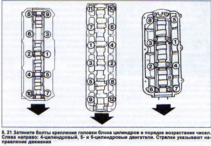
21. Unscrew the cylinder head mounting bolts. The sequence of unscrewing the bolts is the opposite of the tightening sequence (see illustration).
Attention! The cylinder head must be removed from a cold engine. Otherwise, the head removed from a hot engine may "warp" after cooling.
22. Remove the cylinder head together with the intake and exhaust manifolds attached to it, as well as the ignition distributor (five-cylinder engine). If the head is difficult to separate from the cylinder block, loosen its fit by tapping it with a plastic hammer.
Six-cylinder engine
The procedure for removing the cylinder head on this engine is given using the example of the left-hand cylinder head. Removing the head from the right-hand row is done in a similar way.
23. Remove the engine protective cover and the V-belt protective cover.
24. Remove the V-belt, see the relevant chapter.
25. Remove the timing belt, see the relevant chapter.
26. Disconnect the exhaust pipe from the exhaust manifold.
27. Drain the coolant from the engine through the drain hole and from the radiator through the hole at the bottom right.
28. Disconnect the air intake box sleeve (air intake) from the intake manifold.
29. Disconnect the plug from the Hall sensor.
30. Remove the crankcase ventilation hoses from the left and right sides of the cylinder head.
31. Disconnect the air supply hose from the air filter.
32. Disconnect the low pressure air conditioner and/or differential lock hose from the fitting on the left side of the throttle valve.
33. Remove the air intake from the engine compartment together with the crankcase ventilation hoses by pushing the air intake back and then lifting the entire unit upward.
34. Remove the throttle cable retainer, disconnect the cable and set it aside from the work area.
35. Disconnect the connector of the intake air temperature sensor and the idle speed control valve.
36. Disconnect the fuel supply and return hoses.
37. Disconnect the ground (-) wire from the mounting behind the throttle valve fitting.
38. Disconnect the hose from the control unit located in front of the throttle valve fitting.
39. Disconnect the throttle position sensor plug.
40. Disconnect the Evaporative Canister Solenoid Valve hose from the throttle valve fitting on the right side.
41. Remove all spark plug caps
42. Disconnect all valve injector plugs
43. Disconnect the plug of the knock sensor and lambda probe heating.
44. Disconnect the lambda probe plug and put the wires aside.
45. Disconnect the engine oil pressure and temperature sensor plug (on the rear end of the left cylinder head).
46. Disconnect the radiator fan thermal switch plug.
47. Disconnect the hose (blue color) check valve, which is located in the same harness with the brake booster hoses.
48. Disconnect the connectors on the injectors on the left and right sides.
49. Disconnect the hydraulic drive pipe mounting bracket installed on the intake manifold. Do not disconnect the hydraulic drive.
50. Disconnect the intake manifold and remove it.
51. Plug the collector holes with a clean rag.
52. Disconnect the coolant pipe from the rear end of the cylinder head.
53. Disconnect the gas analyzer tube.
54. Remove the lambda probe.
55. Loosen the mounting bolts and remove the exhaust manifold heat shield.
56. Remove the cylinder head cover.
57. Remove the rear timing belt guard.
58. Disconnect the hose from the reservoir to the power steering pump from the cylinder head.
59. Unscrew the cylinder head mounting bolts. The sequence of unscrewing the bolts is the opposite of the order of tightening them (see illustration 8.21).
Attention! Remove the cylinder head from a cold engine. A hot head may "warp" after removal.
60. Remove the cylinder head. If the head does not come off due to a tight fit, tap it with a plastic hammer.
Examination
61. Remove the old sealing gasket. The sealing surfaces of the head and cylinder block must be absolutely clean, without any sealing compound residue.
Caution! Do not clean the sealing surfaces of the cylinder head with sharp tools. The resulting burrs or scratches may cause subsequent damage to the head.
62. Check the cylinder head for warpage. This is especially important if the gasket has burned out.
63. Place a long metal ruler or square along the cleaned sealing surface of the head and use a template to ensure that there is no distortion greater than 0.1 mm. If the distortion is greater than the specified value, the cylinder head should be ground.
Modification of the cylinder head is permitted within certain limits. The permissible minimum height of the head of four-cylinder engines is 132.6 mm, and 5- and 6-cylinder engines 132.75 mm.
Installation
64. Lubricate the hydraulic tappet guides with a thin layer of grease if a new or replacement cylinder head is to be installed.
65. Lubricate the camshaft and install it in place (see the relevant chapter).
Caution! The threads of the cylinder head mounting bolts and the threads of the mounting bolt holes in the cylinder block must be clean and undamaged. Otherwise, the tightening torque of the bolts will not correspond to the nominal one. There must be no oil or liquid in the bolt holes. Failure to do so may result in the metal of the cylinder block being torn.
66. Turn the crankshaft counterclockwise so that none of the pistons are at TDC. Otherwise, when installing the cylinder head, the open valve may hit the piston.
67. Place the cylinder head gasket on the cylinder block so that its marking or the inscription "OBEN" (top) faces the cylinder head.
68. Install the cylinder head. For this purpose, workshops use two guide pins when working with 4- and 5-cylinder engines, which prevent the head itself and the gasket from shifting during installation. Guide pins can be made independently by sawing off the heads of two old head mounting bolts and sawing a slot for a screwdriver. After screwing in several head mounting bolts, these guide pins are unscrewed with a screwdriver, and the mounting bolts are screwed in their place.
69. Screw in all cylinder head mounting bolts and tighten them in the sequence shown in Illustration 8.21. Tightening of the bolts is performed, depending on the engine type, in two or three stages.
Four and five cylinder engines
step 1: Tighten the bolts with a torque wrench to 40 Nm.
step 2: Tighten the bolts with a torque wrench to 60 Nm.
stage 3. Tighten the bolts with a wrench by half a turn, without interrupting the forward movement of the wrench. This operation can be performed in two turns of a quarter turn each. The sequence of tightening the bolts is the same as when screwing them in and tightening them.
Six-cylinder engines
step 1: Tighten the bolts with a torque wrench to 60 Nm.
stage 2. Tighten the bolts with a wrench by half a turn, without interrupting the forward movement of the wrench. This operation can be performed in two additional turns of a quarter turn each. The sequence of turning the bolts is the same as when screwing them in and tightening them.
After completing the turn, the bolts are tightened. Further tightening is not allowed.
When installing the throttle cable and valve injectors on a five-cylinder engine, pay special attention to their correct position.
Caution! Observe the tightening sequence of the intake manifold mounting bolts on six-cylinder engines.
70. Check the ignition timing after complete installation of the cylinder head of four- and five-cylinder engines.
Caution! If the cylinder head was removed due to a damaged head gasket, the coolant must be completely drained and replaced with new coolant. The same applies to replacing the cylinder head.
A faulty cylinder head gasket can be identified by one or more of the following signs:
- a) loss of coolant,
- b) clouds of white gases from the exhaust pipe,
- c) when the engine is running, air bubbles come out of the expansion tank with coolant, and when the tank cap is opened, active leakage of coolant occurs in the form of foam,
- d) grey or brown emulsion on the dipstick due to coolant getting into the engine oil.
Warning! Coolant in the engine lubrication system may cause bearing failure. Replace the cylinder head gasket immediately. Do not start the engine! Deliver the car to the workshop by loading it onto a platform.
A link to the original source is available on the website: audimanual.ru