Table of contents: Cylinder head cover ↓ Installing the cylinder head ↓
Cylinder head. Diesel engines 1.9 l (AVB, AWX, AVF)
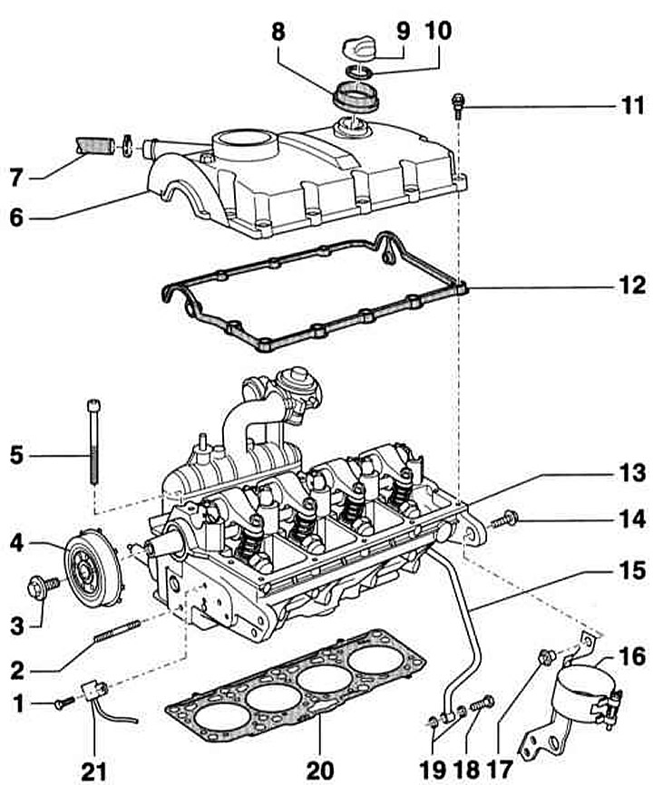
- 1 - Bolt, 10 Nm. Screwed in with thread locking agent
- 2 - Finger, 15 Nm
- 3 - Bolt, 100 Nm. For loosening and tightening, use the AUDI-T10051 anti-rotation tool
- 4 — Hub of the camshaft with gear for the Hall sensor
- 5 — Cylinder head mounting bolt. Be sure to replace. Make sure that washers are installed in the cylinder head.
- 6 — Cylinder head cover
- 7 — Crankcase ventilation hose
- 8 — Lid
- 9 — Lid
- 10 — Seal. If damaged or leaky, replace
- 11 - Screw, 9 Nm
- 12 — Cylinder head cover gasket. Replace if damaged or leaking. Sold only with cylinder head cover. Apply sealant to transitions before installation. Insert bulges into holes in cylinder head
- 13 — Cylinder head
- 14 - Bolt, 20 Nm
- 15 — Oil supply line to turbocharger
- 16 — Fuel filter holder
- 17 — Threaded bushing
- 18 - Hollow bolt, 25 Nm
- 19 — O-ring. Be sure to replace
- 20 — Cylinder head seal
- 21 — Hall sensor for determining the position of the camshaft
Cylinder head attachments. Diesel engines 1.9 l (AVB, AWX, AVF)
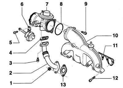
- 1 - Nut, 25 Nm
- 2 — Connecting pipe of the exhaust gas recirculation system
- 3 - Bolt, 22 Nm
- 4 — Seal*
- 5 - Screw, 5 Nm
- 6 — Vacuum drive of the intake manifold flap
- 7 — Inlet manifold with exhaust gas recirculation valve. Can only be replaced as a set
- 8 — Sealing ring*
- 9 - Screw, 10 Nm
- 10 — Inlet manifold
- 11 — Seal*
- Observe the installation position.
- 12 - Bolt, 25 Nm
- 13 — Seal*
*) be sure to replace.
The procedure requires some experience. Only the most important instructions intended for an experienced mechanic are given here.
General installation instructions are given for the 1.6 l ALZ petrol engine.
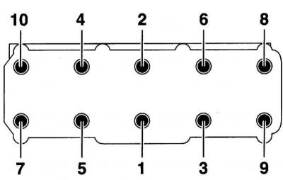
When loosening the cylinder head mounting bolts, follow the sequence.
Cylinder head cover
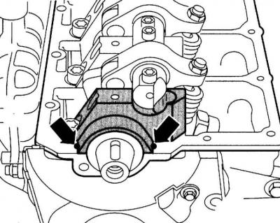
1. Before installing the cylinder head cover, apply to both edges of the sealing surfaces of the camshaft/cylinder head bearing cover at the front (arrows in the accompanying illustration) and at the back one drop of sealant, for example, AMV 174 004 01 (Ø 5 mm).
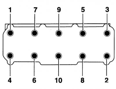
2. The sequence for unscrewing the cylinder head cover mounting bolts is the reverse of that shown in the accompanying illustration.
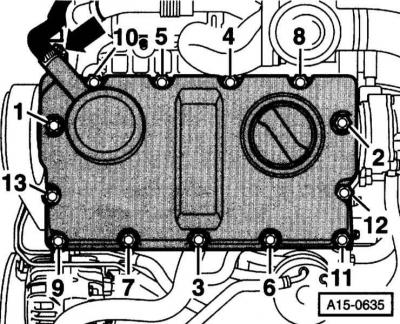
3. Tighten by hand first, in sequence from 1 to 13, and then in the same sequence - to a torque of 9 Nm. The arrow shows the connection of the crankcase ventilation hose.
Installing the cylinder head
1. The cylinder head cover gasket number should be on top.
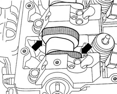
2. When installing the cylinder head, both cams of the first cylinder should point upwards (arrows in the accompanying illustration).
3. Pay attention to the centering bushings in the cylinder block.
4. Tighten the cylinder head bolts in sequence 1 through 10 in 4 steps as given in Specifications efforts.