
Table of contents: Removal ↓ Installation (valve timing… ↓ Timing Belt Tension ↓ Checking the valve timing ↓ If the hub does not lock ↓
The description applies to a toothed belt drive with hydraulic damping of the tension roller. Its feature is the presence of a damper (12). Instructions for a toothed belt drive with a tension roller having friction damping are given at the end of the Chapter.
Toothed belt drive. Diesel engines 1.9 l (AVB, AWX, AVF)
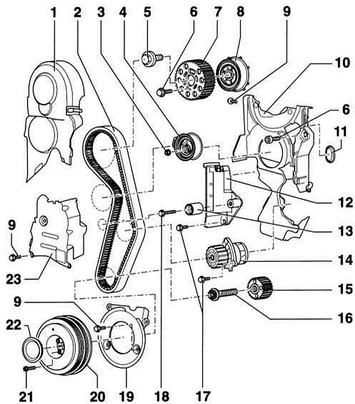
- 1 — Upper toothed belt cover. To remove, remove the air duct to the front panel. When installing, carefully connect it to the central toothed belt cover
- 2 - Toothed belt
- 3 - Nut, 20 Nm + 45°
- 4 — Tension roller
- 5 - Bolt, 100 Nm
- 6 - Bolt, 25 Nm
- 7 - Camshaft wheel. Mark the position
- 8 — Hub with gear for Hall sensor
- 9 - Bolt, 10 Nm. Screwed in with sealant
- 10 - Timing belt cover, rear
- 11 — Rubber bushing. Replace if damaged
- 12 — Belt tensioner damper
- 13 — Guide roller
- 14 — Coolant pump
- 15 — Crankshaft toothed belt wheel. There should be no oil on the mating surface between the toothed belt wheel and the crankshaft. Installation is only possible in one position
- 16 — Bolt*, 120 Nm + 90°. Do not lubricate
- 17 - Bolt, 15 Nm
- 18 - Bolt, 20 Nm
- 19 — Lower timing belt cover
- 20 — Crankshaft wheel (torsional vibration damper). Installation is only possible in one position, the holes are offset
- 21 — Bolt*, 10 Nm + 90°
- 22 — Lid
- 23 — Central toothed belt cover. To remove, remove the upper toothed belt cover and disconnect the V-belt tensioner
*) Be sure to replace.
Removal
1. Set the front panel to the service position, refer to Section Setting the front panel to the maintenance position.
2. Remove the oil level indicator (1) from the guide pipe.
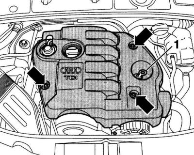
3. Disconnect the covers and unscrew the nuts underneath them (arrows).
4. Remove the top engine cover.
5. Remove the damper underneath.
6. Reinsert the oil level indicator until it stops.
7. Remove the V-belt, refer to Section Removal and installation the accessory drive belt.
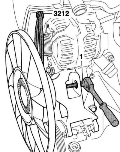
8. Hold the viscous fan pulley with tool 3212 and use an 8 mm socket wrench (1) to loosen it from the holder.
9. Remove the viscous coupling fan and place it in the fan housing.
10. Remove the generator and take the fan with viscous coupling out of the casing, refer to Section Removal and installation the generator.
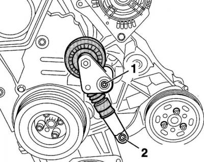
11. Remove screws (1) and (2) and remove the V-belt tensioner.
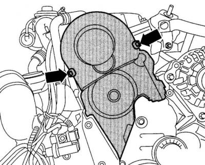
12. Remove the upper timing belt cover.
13. Unscrew the screws (3) and remove the cover (2).
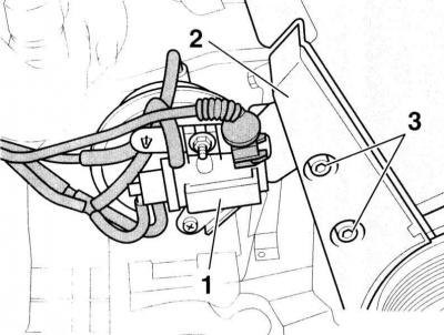
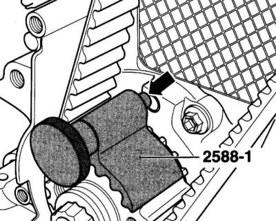
14. Move the boost pressure control solenoid valve (1) to the side.
15. Remove the cover from the crankshaft pulley (torsional vibration damper) and unscrew the pulley.
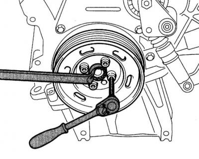
Caution: To loosen and secure the pulley, hold it with a spanner on the center bolt.
16. Disconnect the center and lower timing belt covers (arrows in the accompanying illustration).
Warning: The crankshaft may only be turned in the direction of engine rotation, i.e. clockwise. The crankshaft is turned with a key on the central bolt.
17. Turn the crankshaft and set it to the TDC position of the first cylinder. In this case, the gap between the tabs (1) on the camshaft sensor rotor should lie opposite the "4Z" marking (2) on the rear toothed belt cover.
Warning: For clarity, the accompanying illustration shows the wheel without the timing belt.

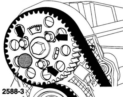
18. Secure the hub with the HAZET 2588-3 pin.
Warning: A 6mm diameter mandrel can be used instead of the specified pin.
19. Secure the crankshaft pulley with the HAZET 2588-1 pin. To do this, insert the special tool (crankshaft stopper) from the end of the toothed belt wheel to its toothed rim.

Caution: The marks on the crankshaft gear (2) and the locking tool (1) must be opposite each other. The tool journal must enter the hole in the sealing flange. If such a tool is not available, mark the sealing flange with the TDC mark.
20. Loosen the mounting bolts (arrows) so that the camshaft wheel rotates in the oblong holes.

21. Insert the socket wrench into the hexagonal hole of the tension roller until it stops and turn the tension roller counterclockwise (direction of the arrow in the accompanying illustration) so that the tensioning device can be secured with the HAZET 2588-2 locking bar.
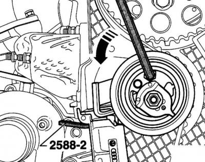
Caution: The socket wrench must be inserted as far as it will go to prevent it from being damaged when turning the tension roller.
Warning: The timing belt tensioner is oil damped and should be pressed evenly without applying significant force.
22. If you are installing a previously used toothed belt, mark the direction of rotation on it with chalk or a felt-tip pen.
23. Unscrew the tension roller mounting nut.
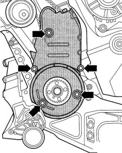
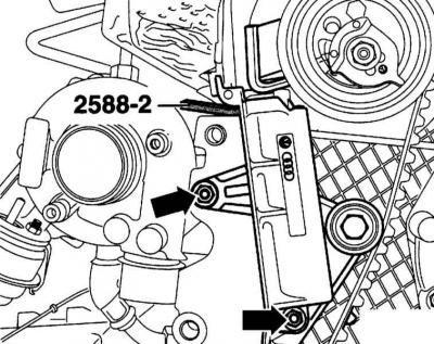
24. Remove the bolts (arrows in the accompanying illustration) timing belt tensioner and remove the tensioner.
25. Remove the timing belt.
Installation (valve timing adjustment)
1. Check whether the camshaft is secured with the HAZET 2588-3 pin, the crankshaft with the HAZET 2588-1 stopper, and whether the timing belt tensioner is secured with the HAZET 2588-2 locking plate.
Warning: Adjustment work on the timing belt may only be performed on a cold engine.
Caution: When turning the crankshaft, do not stop it with any piston at TDC. This can cause damage to the valves and/or piston crowns. If necessary, turn the crankshaft back by 90°.
2. Tighten the bolts by hand.
Warning: The camshaft wheel must rotate and not tip over.
3. Turn the camshaft wheel in its oblong holes until it stops.
4. Place the timing belt on the camshaft sprocket, tension roller, crankshaft sprocket and lastly on the coolant pump sprocket.
5. Install the timing belt tensioner.
Timing Belt Tension
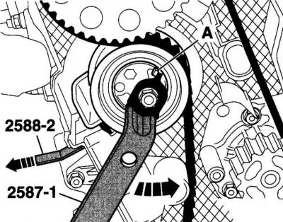
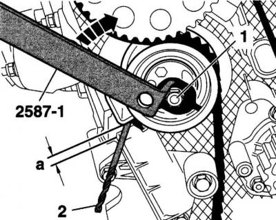
1. Turn the eccentric with the HAZET tool 2587-1 counterclockwise until it stops (A) so that the locking plate HAZET 2588-2 can be removed.
2. Turn the tensioner slowly clockwise (overcoming resistance) so that a drill (2) with a diameter of 4.0 mm can be easily inserted between the tension lever and the housing. Dimension a = 4.0±1.0 mm.

3. While holding the tension roller in this position, tighten the tension roller nut (1) to a torque of 20Nm + 45°.
4. Tighten the bolts (arrows in the illustration) camshaft wheel fastening torque 25Nm.
5. Remove the HAZET 2588-3 locking pin and the HAZET 2588-1 crankshaft stopper.
Caution: The crankshaft may only be rotated in the direction of engine rotation.
6. Turn the crankshaft 2 turns further clockwise so that it again stops at the TDC position of the first cylinder.
7. Check the dimension "a" between the tension lever and the tensioner body again. The required value is: a = 4.0±1.0 mm.
8. If dimension "a" is not achieved, tighten the tension roller as described below.
9. Hold the tension roller with the HAZET 2587-1 tool and loosen the nut (1). Then, using the force of the tensioner, release it so (arrow) that dimension "a" is reached. The required value a = 4.0±1.0 mm.
10. While holding the tension roller in this position, tighten the nut (1) to the torque 20Nm + 45°.
Checking the valve timing
1. To perform the check, secure the timing belt wheel again with the HAZET 2588-1 crankshaft stopper. When doing this, keep the following in mind:
- The marks on the wheel (2) and the crankshaft stopper (1) must be opposite each other. In this case, the crankshaft stopper journal (arrow) must enter the hole in the sealing flange.
- The crankshaft stop pin must enter the hole in the sealing flange when rotating (arrow on the accompanying illustration).
- If the crankshaft has passed the TDC mark of the first cylinder, turn the shaft back 90° so that when rotating in the given direction it again stops in the TDC position of the first cylinder.
Caution: Adjustment by rotating the shaft backwards to set the stopper is not permitted.
2. Check whether the hub is secured using the HAZET 2588-3 locking strip.
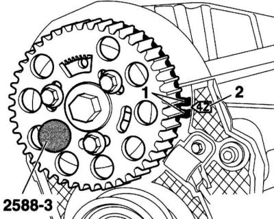
3. The gap between the tabs (1) on the camshaft sensor rotor should be opposite the "4Z" marking (2) on the rear timing belt cover.
If the hub does not lock
1. Loosen the mounting bolts (arrows) of the camshaft wheel.

2. Place a spanner on the central bolt of the camshaft and turn the hub so that the HAZET 2588-3 locking strip can be inserted.
3. Tighten the camshaft wheel mounting bolts (arrows) in this position to a torque of 25Nm.
4. Remove the HAZET 2588-3 locking pin and the HAZET 2588-1 crankshaft stopper.
Caution: The crankshaft may only be turned in the direction of engine rotation, i.e. clockwise.
5. Turn the crankshaft 2 turns in the direction of rotation, i.e. clockwise, so that the crankshaft again reaches the TDC position of the first cylinder.
6. Repeat the valve timing check.
7. Place the viscous coupling fan into the casing.
8. Install the generator in place, while for easier installation of the generator, knock the bushings of the locking bolts back a little, refer to Section Removal and installation the generator.
9. Secure the fan with a viscous coupling with a new bolt to the torque 45Nm.
10. Install the V-belt, refer to Section Removal and installation the accessory drive belt.
11 Replace the front panel, refer to Section Setting the front panel to the maintenance position.