
Table of contents: Timing Belt Tensioner Mechanism ↓ Front camshaft sprocket ↓
Timing Belt Tensioner Mechanism
Removal
1. Disconnect the negative cable from the battery.
2. Apply the handbrake, then jack up the front of the car and support it on axle stands. Remove the lower engine compartment shield and release the front locking lug.
3. Remove the front bumper as described in Section 11.
4. Remove both front headlights as described in Section 12.
5. Disconnect the cable from the hood latch, then unscrew the crossmember bolts from the side panels of the engine compartment and the front brackets and remove it. Also remove the small air duct installed on the radiator.
6. Unscrew the upper radiator mounting bolts and remove the brackets (see Section 2). Do not disconnect the hoses from the radiator.
7. The radiator now needs to be separated from the brackets on the right side and moved forward to create a working space in front of the engine. To do this, remove the bracket bolts on the right side of the radiator, on a 3D engine remove the air ducts, then remove the lower mounting nuts and move the right side of the radiator forward. There is a special Audi bracket designed to hold the radiator away from the engine, but a metal strip or a block of wood will work just fine. Alternatively, you can remove the radiator (see Section 2), which will create a much larger workspace.
8. Remove the accessory drive belt as described in Chapter 7.
9. Remove the fan unit with the heat-viscous coupling (see Section 2). To do this, first unscrew the impeller mounting bolts, then lock the flange/pulley and unscrew the heat-viscous coupling mounting nut. A homemade locking tool can be made from a metal strip with two bolts screwed into one end (the distance between the hole centers on the flange/pulley is approximately 18 mm).
10. Loosen the bolts and remove the auxiliary drive belt tensioner.
11. Turn the crankshaft and the installed engine to the TDC position as described in Chapter 2. This procedure involves removing the fuel pump drive belt and installing the camshaft locking rod. The TDC marks on the flywheel and on the high-pressure fuel pump must align.
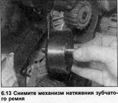
12. Loosen the bolt on the timing belt tensioner mechanism, then turn the mechanism clockwise to reduce the belt tension and tighten the bolt.
13. Loosen the bolt and remove the tensioner mechanism from the cylinder block (see illustration).
Installation
14. Install the tensioner mechanism and insert the bolt, but do not tighten it completely yet.
15. Install and tension the toothed drive belt (see Chapter 4).
16. Install the auxiliary drive belt tensioner.
17. Install the auxiliary drive belt (see Chapter 7).
18. Install the fan unit with the heat-viscous coupling as described in Section 2.
19. Install the radiator as described in Section 2.
20. Connect the hood lock cable and install the crossbar and air duct.
21. Install the headlights and front bumper.
22. Install the lower shield and lower the vehicle to the ground.
23. Connect the battery.
Front camshaft sprocket
Removal
24. Disconnect the negative cable from the battery.
25. Apply the handbrake, then jack up the front of the car and support it on axle stands. Remove the lower engine compartment shield and release the front locking lug.
26. Remove the front bumper as described in Section 11.
27. Remove both front headlights (Section 12).
28. Disconnect the cable from the hood lock, then unscrew the crossmember bolts from the side panels of the engine compartment and the front brackets and remove it. Also remove the small air duct located on the radiator.
29. Unscrew the upper radiator mounting bolts and remove the brackets (see Section 2). Do not disconnect the hoses from the radiator.
30. The radiator now needs to be separated from its mountings on the right side and moved forward to create a work space in front of the engine. To do this, remove the bracket bolts on the right side of the radiator, on a 3D engine remove the air ducts, then remove the lower mounting nuts and move the right side of the radiator forward. There is a special Audi bracket designed to hold the radiator away from the engine, but a metal strip or a block of wood will work just fine. Alternatively, you can remove the radiator (see Section 2), which will create a much larger workspace.
31. Remove the auxiliary drive belt as described in Chapter 7.
32. Remove the fan unit with the heat-viscous coupling (Section 2).
33. Loosen the bolts and remove the auxiliary drive belt tensioner.
34. Turn the crankshaft and set the engine to TDC as described in Chapter 2. This procedure involves removing the fuel pump drive belt and installing the camshaft locking rod. The TDC marks on the flywheel and on the high-pressure fuel pump must align.
35. Loosen the timing belt tensioner mechanism bolt and move the mechanism to relieve the belt tension.
36. Remove the toothed belt from the camshaft sprocket and tensioner mechanism, move it to the side and tie it up so that it does not bend or twist.
Warning: When the timing belt is removed, do not turn the crankshaft or camshaft, otherwise the piston crowns and valves will be damaged.
37. Remove the camshaft cover as described in Chapter 8.
38. Loosen the camshaft sprocket bolt by half a turn, holding the sprocket stationary with a suitable tool. To make one, use two pieces of steel strip (one long, one short) and three nuts and bolts. One bolt connects the two strips so that a forked grip is obtained, the remaining two bolts 3 are inserted into the ends of the grip and into the holes of the sprocket.
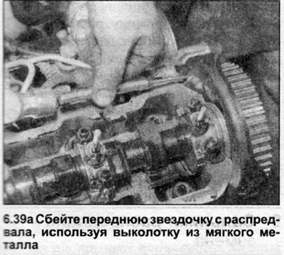
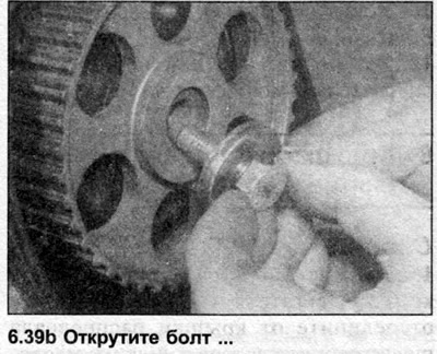
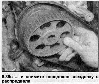
39. Gently knock the sprocket off the camshaft cone by carefully inserting a soft metal drift through the hole in the inner timing belt cover. Remove the bolt and sprocket from the camshaft (see illustrations).
Installation
40. Wipe the contact surfaces of the sprocket and camshaft.
41. Install the sprocket onto the camshaft, insert the mounting bolt and tighten it by hand at this stage so that the sprocket can rotate.
42. Install and tighten the timing belt (see Chapter 4).
43. Install the camshaft cover see. Chapter 8.
44. Install the auxiliary drive belt tensioner and the belt itself (see Chapter 7).
45. Install the fan unit with the heat-viscous coupling as described in Section 2.
46. Install the radiator (Section 2).
47. Connect the hood lock cable and install the crossbar.
48. Install the headlights and front bumper.
49. Install the lower engine compartment shield and lower the vehicle to the ground.
50. Connect the battery.
Rear camshaft sprocket
Removal
51. Remove the fuel pump drive belt as described in Chapter 5.
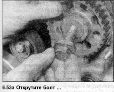
52. Lock the rear sprocket by inserting a suitable tool into the sprocket holes, then loosen the bolt.
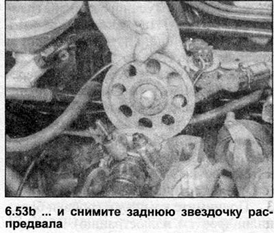
53. Unscrew the bolt and remove the sprocket from the end of the camshaft (see illustrations).
Installation
54. Install the sprocket onto the end of the camshaft and tighten the bolt.
55. Install the fuel pump drive belt (see Chapter 5).
56. Perform the injection timing adjustment procedure as described in Section FOR.
Crankshaft sprocket
Removal
57. Remove the toothed drive belt as described in Chapter 4.
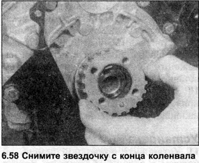
58. Remove the sprocket from the end of the crankshaft (see illustration). If this fails, use two screwdrivers as levers.
Installation
59. Wipe the contact surfaces of the sprocket and crankshaft.
60. Install the sprocket onto the end of the crankshaft, making sure that the projection on its inner side fits into the recess on the shaft. If this is not possible, tap it with a wooden block. Note that the sprocket should not touch the oil pump housing.
61. Install the toothed drive belt as described in Chapter 4.
Fuel pump sprocket
62. See Section 3A.