
Repair Chevrolet Repair Toyota Repair Honda Repair AvtoVAZ Repair Mercedes-Benz Repair BMW Repair Opel
Home  |  Contacts  |  Sitemap  |    
English Русский
Български
Беларускі
Український
Српски
Hrvatski
Română
Polski
Slovenský
Magyar
AudiManual.ru


  • AUDI 80
  • AUDI 100
  • AUDI A3
  • AUDI A4
  • AUDI A6
  • AUDI A8
  • AUDI Q
  • OTHER
  • ARTICLES
C4 (1990-1994) C4 (1990-1994, petrol) C3 (1982-1990) C3 (1982-1990, petrol) C3 (1982-1990, diesel)

Fuel Pump Drive Belt — Removal, Inspection and Installation (Audi 100 C3)

  • Home
  • Audi 100
  • C3 (1982-1990, diesel)
  • Power unit
  • Engine in a car
  • Fuel Pump Drive Belt — Removal, Inspection and Installation
            0
Table of contents: Removal ↓ Inspection ↓ Installation ↓

Removal


1. Remove the cover bolts located on the rear of the engine to gain access to the fuel pump drive belt.

2. Remove the glow plugs to make it easier to crank the engine.

3. With the socket in place on the crankshaft pulley bolt, slowly rotate the crankshaft clockwise until the TDC timing mark on the edge of the flywheel/drive plate aligns with the timing rib on the clutch housing and the timing mark on the fuel pump sprocket aligns with the mark on the pump housing. The moment when piston #1 begins to move in the cylinder can be determined by the sound of air escaping from the #1 glow plug hole. Alternatively, remove the camshaft cover to expose the lobes of cylinder #1. When they both point upwards, piston #1 is at TDC.

Note: Due to the dynamic injection timing setting method (the pump rotates on the mount to make fine adjustments) the TDC mark on the fuel pump pulley may not line up exactly with the mark on the pump housing. In this case, make new timing marks to use when installing the drive belt.


1T engines

Note: The tensioner mechanism is equipped with brackets for the spring needed to tension the drive belt during installation. The spring is actually a special Audi tool, not available to the car enthusiast.


4. Mark the tension of the pump drive belt to facilitate its subsequent installation. Loosen the nut on the belt tensioner to loosen it. Remove the belt from the fuel pump sprockets and camshaft (see illustrations).
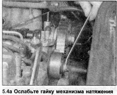
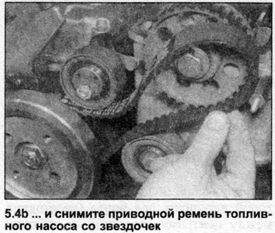

4. Mark the tension of the pump drive belt to facilitate its subsequent installation. Loosen the…


4. Mark the tension of the pump drive belt to facilitate its subsequent installation. Loosen the…


3D Engines

5. On 3D engines, lock the fuel pump sprocket by inserting a pin through its mounting hole into the pump housing. Lock the sprocket onto the rear end of the camshaft using a suitable tool (see Chapter 6), then unscrew the mounting bolt and remove the sprocket and drive belt. Remove the belt from the fuel pump sprocket.
5. On 3D engines, lock the fuel pump sprocket by inserting a pin through its mounting hole into the…


Inspection


6. If the belt is contaminated with coolant or grease, find the source and correct the cause. Inspect the belt for damage and signs of wear, especially around the drive edges of its teeth. Replace the belt if there is any doubt about its condition; the cost of replacing the belt is insignificant compared to the cost of engine repairs that would be required if the belt broke while driving. The belt should also be replaced if the car has traveled the distance specified by the manufacturer since its installation.

Installation


1T engines

7. Position the tensioner with the lever facing up so that the tensioner presses on the drive belt when the spring is attached. The nut should be loosened one full turn to allow the tensioner to move freely.

8. Make sure the TDC timing marks on the flywheel/drive plate and fuel pump are still aligned

9. Install the drive belt on the camshaft and fuel pump sprockets and route it over the idler pulley and tensioner pulley. The lower run of the belt should be taut and the slack should be below the tensioner.

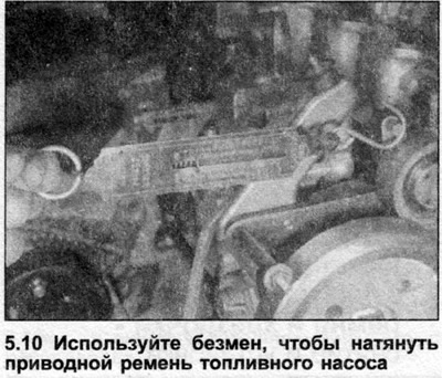
10. If possible, attach a special spring to the tensioner lever and tighten the drive belt. If a special spring is not available, ask an assistant to attach a spring balance to the lever and apply a pulling force of approximately 2.5 kg (see illustration). While holding the spring balance in this position, rotate the crankshaft approximately one-half turn clockwise, then tighten the tensioner nut to the tightening torque specified in the Specifications.


11. Check and, if necessary, adjust the injection timing as described in Section 3A.

12. Screw in the glow plugs, then install the drive belt cover and tighten the bolts.

3D Engines

13. Route the drive belt over the fuel pump sprocket, then place the camshaft sprocket into the belt and install it onto the shaft.

14. Insert the bolt and tighten it to 50 Nm, holding the sprocket stationary (see Chapter 6). The locking pin is still inserted into the fuel pump sprocket, so it is important not to put tension on the drive belt while tightening the bolt.

15. Loosen the bolt approximately half a turn and check that the sprocket turns freely on the camshaft.

16. Check the drive belt tension. There is a special Audi tool designed for this purpose. If the tool is not available, use the fact that the correct tension is such that the belt can be twisted by fingers only 90° at the midpoint of the run between the camshaft and fuel pump sprockets.

17. Make sure the TDC timing marks are still aligned, then tighten the camshaft sprocket bolt to Specifications while holding the sprocket stationary.

18. If the drive belt tension is incorrect, move the fuel pump bracket to the cylinder block by loosening its bolts. After completing the adjustment, tighten the bolts to the tightening torque specified in the Specifications, and then repeat the belt tensioning procedure.

19. Check and, if necessary, adjust the injection timing as described in Section FOR.

20. Screw in the glow plugs, then install the drive belt cover and tighten the bolts.
The article was checked by auto expert Nikita Rudakov
This article is available at russian, bulgarian, belarusian, ukrainian, serbian, croatian, romanian, polish, slovak, hungarian

Share information:
Previous articles
Audi 100 C3: Engine in a car
Next articles

Toothed drive belt — removal, inspection and installation
Checking the compression in the cylinders
Valve timing marks — general description and use
General description
Timing Belt and Sprocket Tensioner Mechanism — Removal and…
Auxiliary drive belt — removal, installation and tensioning
Camshaft Cover — Removal and Installation
Camshaft Seals — Replacement


Similar articles on other Audi car models:
Mechanical fuel pump — removal and installation Audi 80 B3 (1986-1991, petrol)
Control unit for Motronic, fuel pump relay, injectors... Audi A3 Type 8L (1996-2003)
Oil pump drive, high-pressure fuel pump and balance shaft Audi A4 B8 (2007-2015)
Fuel pump drive belt Audi A6 C4 (1994-1997)
Fuel pump / fuel level sensor Audi A8 D2 (1994-2002)
Removal and installation the fuel injection pump drive belt Audi Q7 Typ 4L (2005-2015, diesel)
Removal and installation the crankshaft belt drive pulley Audi A2 (1999-2005)
Link to this page in different formats


Visitor comments

No comments yet


How much will 42 + 38 =


100(C4, 1990-1994) 
  • General information
  • User manual
  • Power unit
  • Engine repair
  • Ignition system
  • Fuel system (gasoline)
  • Fuel system (diesel)
  • Lubrication system
  • Cooling system
  • Exhaust system
  • Transmission
  • Clutch
  • Car gearbox
  • Drive shafts
  • Chassis
  • Car suspension
  • Steering
  • Wheels and tires
  • Brake system
  • Body
  • Ventilation and heating
  • Body repair
  • Electrical equipment
  • Power devices
  • Lighting and appliances
  • Electrical circuits
 
100(C4, 1990-1994, petrol) 
  • General information
  • Operation and maintenance
  • Power unit
  • Engine repair
  • Exhaust system
  • Cooling system
  • Supply system
  • Air filter
  • Mono-Motronic injection system
  • Digifant injection system
  • KE-III-Jetronic and KE-Motronic
  • MPI and MPFI injection system
  • Transmission
  • Clutch
  • Car gearbox
  • Chassis
  • Suspension and steering
  • Brake system
  • Wheels and tires
  • Body
  • Exterior
  • Interior
  • Electrical equipment
  • Fuses and relays
  • Power devices
  • Ignition system
  • Lighting and signaling
  • Equipment and devices
  • Electrical circuits
 
100(C3, 1982-1990) 
  • General information
  • User manual
  • Maintenance
  • Specifications
  • Power unit
  • Engines 4-cylinder
  • Engines 5-cylinder
  • Diesel engine
  • Cooling system
  • Power system (carburetor)
  • Power system (injector)
  • Fuel system (diesel)
  • Transistor ignition system
  • Electronic ignition system
  • Transmission
  • Clutch
  • 4 speed gearbox 014
  • 5 speed gearbox 013 and 093
  • 5 speed gearbox 016 and 012
  • Shift mechanism KP 016
  • Automatic transmission
  • Front wheel drive
  • Chassis
  • Front suspension
  • Rear suspension
  • Steering
  • Brake system
  • Body
  • Body elements
  • Electrical equipment
  • Lighting and appliances
  • Power devices
  • Electrical circuits
 
100(C3, 1982-1990, petrol) 
  • General information
  • Maintenance and operation
  • 4 cylinder engine
  • Engine repair
  • Cooling and lubrication system
  • Supply system
  • Ignition system
  • 5 cylinder engine
  • Engine repair
  • Cooling and lubrication system
  • Supply system
  • Ignition system
  • Transmission
  • Clutch and drive shafts
  • 4 speed gearbox 014
  • 5 speed gearbox 013 and 093
  • 5 speed gearbox 016 and 012
  • Automatic gearbox
  • Chassis
  • Steering
  • Front suspension
  • Rear suspension
  • Brake system
  • Body
  • Body elements
  • Doors, locks and windows
  • Body repair
  • Electrical equipment
  • Equipment and devices
  • Power devices
  • Electrical circuits
 
100(C3, 1982-1990, diesel) 
  • General information
  • User manual
  • Maintenance
  • Troubleshooting
  • Power unit
  • Engine in a car
  • Engine removed
  • Cooling system
  • Fuel system
  • Exhaust system
  • Starting and charging
  • Preheating
  • Transmission
  • Clutch
  • Mechanical gearbox
  • Automatic gearbox
  • Drive shafts
  • Chassis
  • Brake system
  • Suspension
  • Steering
  • Body
  • Exterior
  • Interior
  • Electrical equipment
  • Equipment and devices
  • Electrical circuits
 
AudiManual.ru © 2017-2026 · Mobile version · Feedback · Sitemap: EN BG BY UA RS HR RO PL SK HU · Site search · News and articles
80 B2 · 80 B3 petrol · 80 B3 · 80 B4 · 100 C3 diesel · 100 C3 petrol · 100 C3 · 100 C4 petrol · 100 C4 · A3 Type 8L · A4 B5 petrol · A4 B5 · A4 B6 petrol · A4 B6 · A4 B7 · A4 B8 · A6 C4 · A6 C5 · A6 C5 Allroad · A8 D2 · Q5 Type 8R · Q7 Typ 4L · Audi A2 ·
This site uses cookies 🍪. Click the button to accept this fact.