
Note: Observe the precautions given in Chapter 1. For the initial installation of the fuel pump you will need a suitable micrometer and adapter.
Removal
1. Disconnect the negative cable from the battery.
2. Where necessary, loosen the nuts and remove the cover from the top of the engine.
3. Remove the camshaft cover as described in Section 1A.
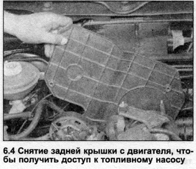
4. Loosen the mounting bolts and remove the cover from the rear of the engine to gain access to the fuel pump drive belt (see illustration).
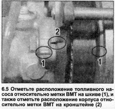
5. Set piston No.1 to TDC position as described in Section 1A, however, before removing the fuel pump drive belt and sprocket at the rear of the camshaft, note the location of the TDC mark on the fuel pump sprocket/pulley in relation to the pump body. Also note the location of the fuel pump in relation to the bracket (see illustration). Cm. Section 1A for the fuel pump drive belt removal procedure, however, it is not necessary to install the locking rod, as this is only required when performing the toothed drive belt installation procedure.
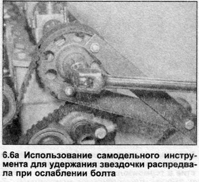
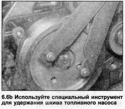
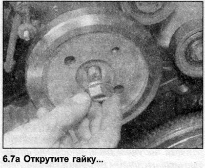
6. Loosen the bolt/nut securing the sprocket and pulley to the camshaft and fuel pump drive shaft by one to two turns. To do this, hold each sprocket using a suitable tool (see illustrations).
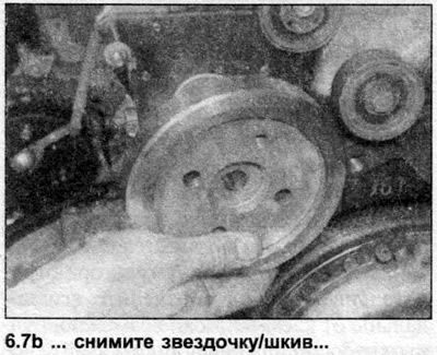
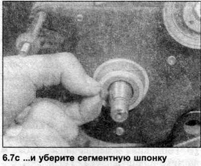
7. To remove the fuel pump sprocket, screw a suitable extractor onto it. Once the sprocket is free, completely unscrew the nut and remove the sprocket. Remove the woodruff key from the drive shaft (see illustrations).
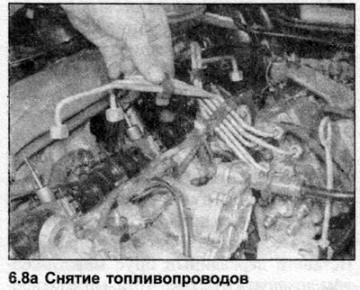
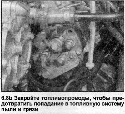
8. Loosen the union nuts securing the fuel lines to the injectors and high-pressure fuel pump and remove them as a complete set. Seal the fuel lines to prevent dust and dirt from entering the fuel system (see illustrations).
9. Loosen the coupling bolts and disconnect the fuel supply and return hoses from the fuel pump.
10. Remove the seal washers.
11. Note the location of the electrical wiring on the high pressure fuel pump, then disconnect it.
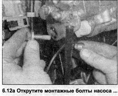
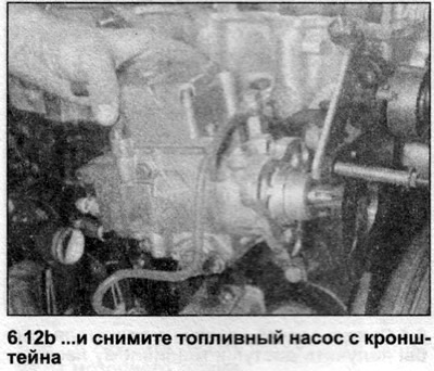
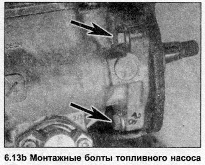
12. Mark the location of the fuel pump relative to the bracket to facilitate installation. Loosen the pump mounting bolts and remove the fuel pump from the bracket (see illustrations).
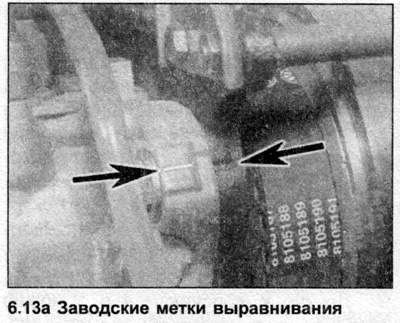
13. Position the fuel pump on the bracket and insert the mounting bolts. Rotate the pump as necessary until the mounting bolts are centered in the elongated holes in the bracket, then tighten the bolts to the specified torque Specifications. The factory alignment marks should be aligned at this stage (see illustrations). These marks will remain aligned for static injection timing adjustment, but during dynamic injection timing adjustment the fuel pump may be moved so that the marks are no longer aligned with each other.
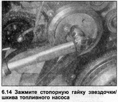
14. Install the fuel pump sprocket/pulley and woodruff key onto the drive shaft and tighten the nut to the specified torque Specifications, holding the sprocket with the tool used to remove it (see illustration).
15. Install the sprocket on the rear of the camshaft, insert the bolt with the washer, and tighten it to the specified tightening torque Specifications, holding the sprocket with the tool.
16. Install and tension the fuel pump drive belt as described in Section 1A. Please note that precise adjustment of the injection timing depends on the correct installation and tension of the drive belt.
17. Reset the engine and fuel pump to TDC, then loosen the sprocket bolt on the rear of the camshaft one turn so that the sprocket can be turned freely on the camshaft.
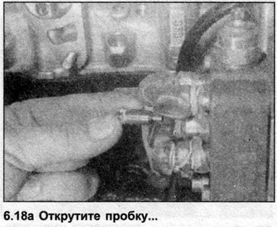
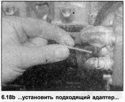
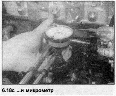
18. Loosen and remove the injection timing adjustment plug on the front of the fuel pump and install a micrometer. You will need a suitable adapter (see illustrations).
19. Make a preliminary setting so that the micrometer shows 1 mm. Then determine the BDC position of the pump piston by slowly turning the fuel pump pulley in both directions. Note that the TDC mark on the pulley is the TDC mark for the engine, but in fact, at this position the pump piston starts to rise from the BDC position. This can be a little confusing, so it is important to watch the movement of the micrometer needle to ensure that the pump is accurately set at BDC. The fuel pump can be turned using a suitable tool inserted into the holes in the sprocket on the back of the camshaft.
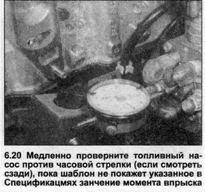
20. With the pump at BDC, reset the micrometer reading to zero, then slowly turn the fuel pump counterclockwise (if you look from behind), until the micrometer shows the value specified in Specifications value for injection moment (after BDC) of fuel pump piston (see illustration).
21. Check that the TDC mark on the flywheel/drive plate is aligned with the slot in the transmission, then carefully tighten the bolt securing the sprocket to the rear of the camshaft to the specified torque Specifications. While doing this, hold the sprocket with a tool. Try not to disturb the installation of the fuel pump.
22. Rotate the crankshaft two full turns clockwise and align the TDC marks on the flywheel/drive plate and transmission. Do not rotate the crankshaft beyond the TDC marks.
23. Note the result obtained on the micrometer. Due to the tension of the toothed drive belt, the result obtained will be slightly less than the derived value. If the result obtained is outside the specified limits, repeat the installation procedure.
24. Remove the micrometer and adapter, then install and tighten the plug to the specified tightening torque Specifications.
25. Connect the wiring to the fuel pump.
26. Connect the fuel supply and return hose couplings together with new washers and tighten the couplings to the specified tightening torque Specifications.
27. Connect the fuel lines to the injectors and high-pressure fuel pump and tighten them to the specified tightening torque Specifications.
28. Install the fuel pump cover to the rear of the engine.
29. Install the camshaft cover as described in Section 1A.
30. Connect the negative cable to the battery.
31. Ideally, the fuel pump should now be primed. To do this, disconnect the fuel return coupling from the top of the pump, and connect a vacuum pump with a 1.0 meter long plastic tube via an adapter. Pump the vacuum pump until fuel flows from the return port. Be careful that no fuel gets into the vacuum pump. Finally, connect and tighten the fuel return coupling.
32. Start the engine and check the fuel system for leaks.