
Note: Observe the precautions given in Chapter 1.
Warning: Handle fuel injectors with extreme caution. Never place your hands or any part of your body under the injector jet. It is strongly recommended that any work involving pressure testing of injectors be performed by a fuel injection system specialist or dealer. Before starting work, refer to the precautions given in Chapter 1 from this Section.
General description
1. Injectors wear out with long-term use, and it is reasonable to expect that they will need repair or replacement after 100,000 km of run. An accurate check of serviceability, overhaul and calibration of injectors should be entrusted to a specialist. A defective injector, which may be the cause of detonation or smoking, can be identified without disassembling as follows.
2. Start the engine, set the fast idle mode. Gradually loosen the coupling sleeve on each injector in turn. When the coupling sleeve on the defective injector is loosened, detonation or smoking should stop.
Removal
Note: Work very carefully, do not allow dirt to get into the injectors or fuel lines. Do not drop the injectors!
3. Disconnect the negative cable from the battery.
4. Where applicable, remove the top cover from the engine.
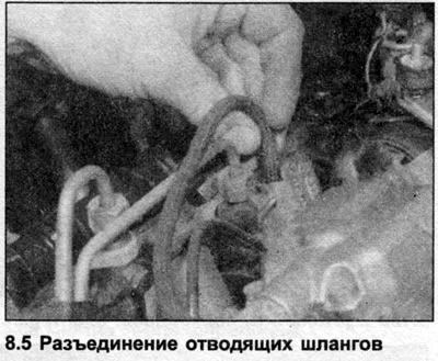
5. Carefully clean the area around the injectors and fuel line coupling nuts and disconnect the outlet hoses from the injectors (see illustration).
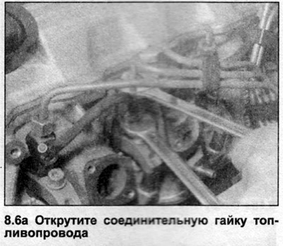
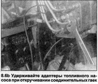
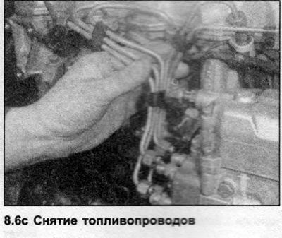
6. Wipe the fuel line couplings clean, then loosen the union nuts securing the tubes to each injector, as well as the union nuts securing the tubes to the back of the fuel pump (the tubes are removed as one assembly). Remove the injector tubes from the engine. Cap the injector and fuel line couplings to prevent dirt from entering the system (see illustrations).
7. Access to injectors 4 and 5 can be gained by removing the expansion element bracket and the idle speed control mechanism bracket.
8. Clean the area around the base of the injectors, then unscrew them and remove them from the cylinder head.
Warning: Make sure you unscrew the injector retainer from the cylinder head and remove the entire assembly, not the injector body from the retainer. If the body is unscrewed from the retainer, the small internal components of the injector will be disturbed and a professional will be required to reassemble and inspect the injectors.
9. Remove the fireproof washers from the injector seats in the cylinder head.
Installation
10. Clean the injector seats and the threads in the cylinder head.
11. Install new fire washers into the cylinder head, making sure they are oriented correctly. The outer rim of the washers should be facing up.
12. Apply a small amount of anti-seize compound to the threads of the injectors, then screw them into the cylinder head and tighten them to the tightening torque specified in the Specifications.
13. Install the idle speed control mechanism and expansion element brackets and tighten the bolts.
14. Connect the tubes to the injectors and fuel pump, and tighten the nuts.
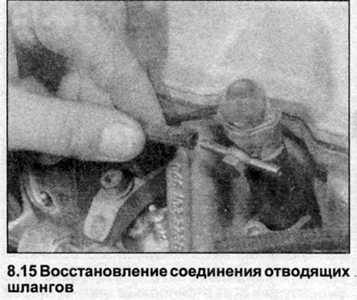
15. Connect the outlet hoses and tighten the clamps where necessary (see illustration).
16. Where applicable, install the top cover onto the engine.
17. Connect the wiring to the battery.
(A link to the original source is available on the website: AudiManual.ru)