
Table of contents: Removal ↓ Installation and adjustment ↓
Application: Before starting work, read the warnings in paragraph 1. Before initial setting of the injection timing, a dial indicator head and a suitable adapter are required.
Removal
1. Disconnect the negative battery cable as described in chapter 5A, move it away from the output.
2. Unscrew the nuts and remove the plastic cover from the top of the engine.
3. Remove the upper timing belt cover.
4. Remove the valve cover - see chapter 2B.
5. Set the piston of the first cylinder to TDC of the compression stroke, as described in chapter 2B. To perform this procedure you will need a camshaft locking bar.
6. Unscrew the connection bolts and remove the fuel lines from the high-pressure fuel pump. Note that the return line connection bolt has a built-in non-return valve (Fig. 6.6). Remove the sealing washers.

7. Hang tags on the wiring connectors and disconnect it from the fuel injection pump.
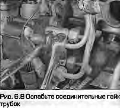
8. Unscrew the connecting nuts of the fuel pipes to the injectors and the high-pressure fuel pump and remove them as a set (Fig. 6.8). When unscrewing the high-pressure fuel pump fittings, hold them with an open-end wrench. Try not to bend the pipes.
9. Plug the holes in the tubes, nozzles and fuel injection pump fittings to prevent dirt from getting in.
10. Remove the timing belt tensioner as described in chapter 2B.
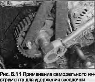
11. Attach a suitable tool to the fuel injection pump sprocket to hold it (Fig. 6.11).
12. Loosen the fuel injection pump sprocket mounting nut by one turn.
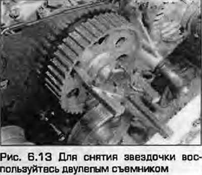
13. Using a suitable puller, remove the sprocket from the injection pump shaft (Fig. 6.13). When using the puller, do not apply great force or knock on the shaft to avoid damaging the pump.
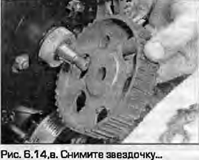
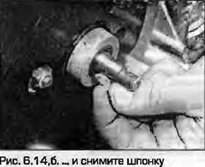
14. Unscrew the nut completely and remove the sprocket. Remove the key from the slot on the shaft (Fig. 6.14).
 |
 |
15. To facilitate installation, mark the position of the pump on the bracket. Unscrew the front bolts securing the pump to the bracket. Access to the two inner bolts is possible from the front of the rear cover of the injection pump. Access to another bolt is possible from the injection pump side of the bracket.
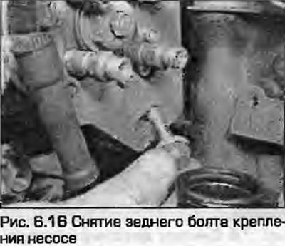
16. Unscrew the rear mounting bolt and remove the pump from the mounting bracket (Fig. 6.16).
Installation and adjustment
17. Mount the pump to the bracket and tighten the rear mounting bolt. Tighten the bolt and cone nut to the specified torque to center the pump.
18. Turn the pump to center it in the oblong holes in the front of the bracket, install the front mounting bolts and tighten them "finger tight" at this stage. If installing the previous pump, align the pre-marked marks and tighten the mounting bolts.
19. Insert the key into the slot on the pump shaft, put on the sprocket and tighten the nut. Holding the sprocket still with the tool used when unscrewing, tighten the nut to the specified torque.
20. Align the holes intended for installing the pump in the position corresponding to the TDC of the compression stroke of the first cylinder and insert the locking pin into them.
21. Install the timing belt and tensioner as described in chapter 2B.
22. Before connecting the wiring and fuel lines, perform the following adjustment.
23. Make sure that all TDC marks are aligned, remove the camshaft retaining plate and the pin from the fuel injection pump sprocket.
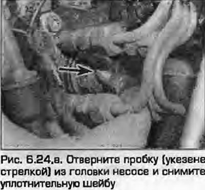
24. Unscrew the plug in the rear of the fuel pump, remove the sealing washer and screw in the adapter (adapter) with the indicator head (Fig. 6.24).
 |
 |
25. Wind the indicator by 2 mm and smoothly turn the crankshaft counterclockwise until the indicator arrow stops. Wind the indicator by 1 mm. Zero the scale.
26. Slowly turn the engine clockwise until the mark on the flywheel/faceplate aligns with the indicator on the bell cutout. Do not turn the crankshaft further - the indication may be lost and the procedure will have to be repeated.
27. Indicator reading (plunger lift) in this position (initial injection advance) should be 0.7±0.2 mm.
28. If adjustment is required, loosen the pump mounting bolts by one turn and turn the pump until the required reading is achieved.
29. Tighten the pump mounting bolts to the specified torque, repeat the procedure and check the accuracy of the indicator readings.
30. Remove the indicator, screw in and tighten the plug with a new seal.
31. Install the fuel pipes between the injectors and the pump and tighten their nuts to the specified torque.
32. Connect the electrical wiring connectors to the pump.
33. Install the fuel lines by tightening the connection bolts with new sealing washers and tightening them to the specified torque. The bolt with the non-return valve is from the return line.
34. Install the valve cover as described in chapter 2B. Install the outer timing belt cover.
35. Connect the battery as described in chapter 5A.
36. Now the fuel injection pump must be bled with a hand pump. To drain fuel from the fuel injection pump, the Audi vacuum pump has a built-in container. Attach the pump to the return nipple of the fuel injection pump and pump until bubbles stop coming out of the pump. Do not allow fuel to enter the vacuum pump.
37. Connect the return line to the pump, start the engine and check for leaks.
38. Now it is necessary to check the dynamic injection advance. This requires specialized diagnostic equipment. Contact the dealer for assistance.
39. After completing the adjustment, always loosen the fuel line connection nuts and tighten them again to relieve stress that could cause them to break due to constant vibration.
40. Install the upper plastic engine cover.
(This article was previously published on the resource: AudiManual)