
Table of contents: Coolant temperature sensor ↓ Engine speed sensor ↓ Fuel shut-off valve ↓ Injection start valve ↓ Boost Pressure Control Valve ↓ Intake Air Pressure/Temperature… ↓ Air flow sensor (MAF) ↓ Electronic control unit (ECU) ↓ Glow Plug and Relay System Fuse Box ↓ Brake and clutch pedal switches ↓ Fuel temperature sensor ↓
Note: Before doing any work, please read the warnings contained in paragraph 1.
Coolant temperature sensor
Removal
1. The temperature sensor is installed at the rear of the cylinder head.
2. As described in chapter 1B, drain approximately a quarter of the coolant from the engine.
3. Disconnect the wiring and unscrew the sensor.
Installation
4. Installation - reverse procedure. Top up with coolant as described chapter 1B.
Engine speed sensor
Removal
5. The sensor is installed on the left wall of the cylinder block, closer to the bell.
6. Trace the sensor wiring to the connector and disconnect it.
7. Loosen the mounting screw and remove the sensor from the unit.
Installation
8. Installation - reverse procedure.
Fuel shut-off valve
Removal
9. The valve is installed on top of the fuel injection pump distributor head. First, clean the area around the valve to prevent dirt from getting into the system.
10. Unscrew the nut and disconnect the wiring.
11. Unscrew the sensor and remove the sealing ring, spring and plunger.
Installation
12. Installation - reverse procedure. Install clean components and tighten the sensor to the specified torque.
Injection start valve
Removal
13. The valve is installed under the distributor head on the high-pressure fuel pump. First, clean the area around the valve to prevent dirt from getting into the system.
14. Loosen the screw and remove the valve from the pump. Be prepared for fuel spillage.
15. Remove the sealing ring, filter, inner sealing ring.
16. Disconnect the wiring connector.
Installation
17. Installation - reverse procedure. Install clean components and tighten the screw securely.
Boost Pressure Control Valve
Removal
18. The valve is secured behind the right headlight. Disconnect the plastic air duct from the intake duct leading to the air filter.
19. Disconnect the wiring.
20. Remove the vacuum hoses, remembering the order in which they were installed so as not to scare them during assembly.
21. Unscrew the mounting nuts and remove the valve.
Installation
22. Installation - reverse procedure.
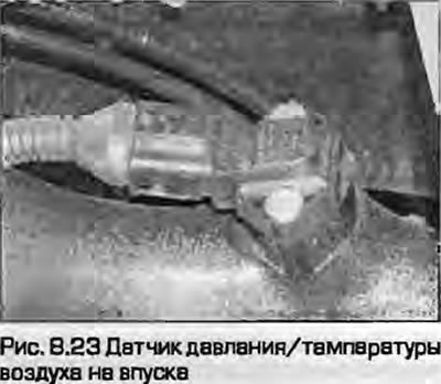
Intake Air Pressure/Temperature Sensor
Removal
23. The sensor is installed in the intake air duct leading from the intercooler to the intake manifold in the left rear part of the engine compartment (Fig. 8.23). Disconnect the wiring.
24. Loosen the screws and remove the sensor from the air duct.
Installation
25. Installation is the reverse procedure.
Air flow sensor (MAF)
Removal
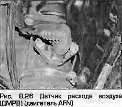
26. The sensor is installed in the upper cover of the air filter (Fig. 8.26).
27. Disconnect the plastic air duct from the air filter.
28. Loosen the clamp and disconnect the air inlet hose from the sensor.
29. Unhook the latches and remove the cover from the air filter housing together with the sensor. Disconnect the wiring from the sensor and remove the unit.
30. The sensor with the screen can be removed from the cover, as well as the intermediate air duct. Handle the sensor carefully - it is fragile. Remove the sealing ring.
Installation
31. Installation - reverse procedure.
Electronic control unit (ECU)
Warning: Before disconnecting the connector, wait at least 30 seconds after switching off the ignition. When disconnecting the connector, all set data is erased. but possible fault codes are stored in the memory. After connecting the connector, it is necessary to program the basic settings. for which specialized Audi/VAG equipment is required. When replacing the ECU, it is also necessary to enter the identification code of the new unit into the immobilizer memory. Contact the dealer for assistance.
Removal
32. The electronic control unit is installed on the engine shield in the rear part of the engine compartment. On right-hand drive models it is located on the right, on left-hand drive models it is located on the left.
33. Disconnect the ground cable from the battery as described in chapter 5A.
34. Loosen the screws and remove the cover.
Note: On early left hand drive models there is a hole in the cover panel in front of the windshield to access the mounting bolt, on later models there is no hole - the panel must be removed.
35. Use a screwdriver to release the spring clip and lift the ECU upwards.
Note: On some models it will be necessary to remove the additional relay box and additional fuse box.
36. Release the retainer and disconnect the wiring connector from the unit.
Warning: After turning off the ignition, wait at least 30 seconds before disconnecting the connector.
37. Remove the block from the engine shield. If necessary, the mounting housing can be removed by unscrewing the mounting nuts and releasing the tongue from the guide hole.
Installation
38. Installation - reverse procedure. Press the lock until it clicks and gradually tighten the mounting screws. Connect the battery as described in chapter 5A.
Glow Plug and Relay System Fuse Box
Removal
39. The system relays are installed under the ECU cover. Disconnect the ground wire from the battery as described in chapter 5A.
40. Loosen the screws and remove the cover.
41. To remove the relay, pull it straight out of the fuse box. To remove the fuse box, disconnect the wiring and unscrew the mounting bolts.
Installation
42. Installation - reverse procedure.
Brake and clutch pedal switches
43. The sensors send signals to the ECU, which are used to set the dynamic injection advance angle. In chapters 6 and 9 information on their removal and installation is provided.
Fuel temperature sensor
Removal
44. The sensor is installed on top of the fuel injection pump, under the cover.
45. Loosen the screws and remove the cover from the high-pressure fuel pump. Remove the gasket.
46. Loosen the screws and remove the sensor.
Installation
47. Installation is the reverse procedure. Securely tighten the cover mounting screws.
The original version is on the portal Audimanual.ru