
Table of contents: General information ↓ Setting piston #1 to TDC ↓
General information
1. The sprockets of the camshaft, crankshaft, fuel injection pump and auxiliary shaft are driven by a toothed belt and rotate in phase.
2. The design of the engines discussed in this chapter is such that when the timing belt is removed, the pistons rest against the valves when the crankshaft rotates. Therefore, it is important to maintain the relative positions of the crankshaft, camshaft and (if provided) auxiliary shaft with the timing belt removed. This is achieved by setting the engine in a certain position (called TDC - top dead point) before removing the timing belt and preventing the shafts from turning. For the same purpose, when repairing the engine, the engine must be set to TDC, restoring the correct phasing of the shafts.
3. TDC - the highest point reached by the piston of the corresponding cylinder (in a four-stroke engine, twice per stroke; one cut in the compression stroke and the other in the exhaust stroke). Usually (unless otherwise stated) this means TDC of the first cylinder in the compression stroke. The cylinders are numbered from 1 to 4, starting from the timing belt.
Setting piston #1 to TDC
4. Remove the valve cover and accessory belts as described in paragraphs 7 and 6 respectively. Remove the outer timing belt cover as described in paragraph 4. Remove the glow plugs as described in Chapter 5B to make the engine easier to turn.
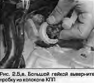
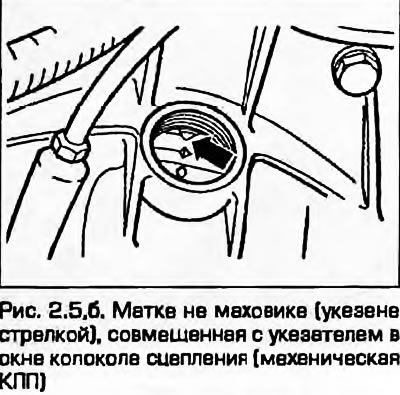
5. If provided, remove the plug to check the mark in the gearbox bellhousing, using a nut or bolt head if necessary (fig. 2.5, a, b). Turn the crankshaft clockwise using a head with a ratchet until the TDC marks on the flywheel/faceplate are aligned with the indicator in the hole on the bell housing and the hole on the fuel injection pump sprocket is aligned with the hole on its mounting bracket.
 |
 |
Note: On the ANN engine, the hole in the bracket must be aligned with the cutout on the inside of the sprocket.
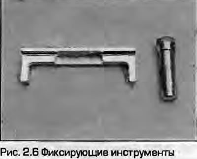
6. To lock the engine in this position, you need to lock the camshaft (not his star) and the TN8D sprocket in the appropriate positions using special fixing tools, you can make a homemade tool, but to maintain accuracy, it is strongly recommended to purchase a branded tool from an Audi/VAG dealer (Fig. 2.6).
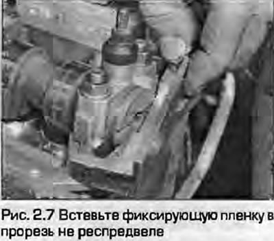
7. Align the projection of the locking bar with the slot in the camshaft heel (Fig. 2.7).
8. After installing the locking bar into the camshaft groove, carefully turn it slightly (rotating the crankshaft clockwise) so that the locking bar rests against the surface of the cylinder head. Measure the gap between the opposite end of the bar and the surface of the head using a set of flat feeler gauges.
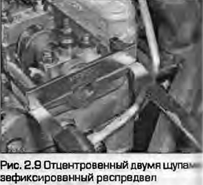
9. Carefully turn the camshaft back, pull out the feeler gauge. The further development of the idea is to install two feeler gauges of the same thickness, equal to half the measured gap, on both sides of the locking bar between it and the cylinder head. In this way, the camshaft will be set to the position corresponding to the TDC of the compression stroke of the first cylinder (Fig. 2.9).
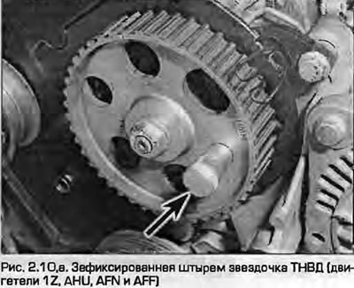
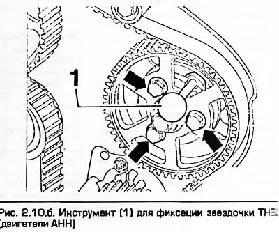
10. Insert the locking pin into the mounting holes (or cutout) of the fuel injection pump sprocket and its mounting bracket. This cut will set the pump to the position corresponding to the TDC of the compression stroke of the first cylinder (fig. 2.10, a, b).
 |
 |
11. Now the engine is set to TDC of the compression stroke of the first cylinder.
Material republished from the website: Audimanual.ru