
Removal
1. The main purpose of the belt is to drive the camshaft. If the belt breaks or comes off while the engine is running, the valve timing will be disrupted, the pistons will hit the valves - there will be a serious breakdown. Therefore, it is very important for the belt to be properly tensioned. It is necessary to check the condition of the timing belt regularly.
2. The procedure for removing the rear timing belt cover is described as part of the cylinder head removal procedure in paragraph 11 this chapter.
3. Disconnect the battery by disconnecting its negative cable (see chapter 5A). Remove the top engine cover.
4. Apply the handbrake, raise the front of the vehicle and install safety stands. If necessary, remove the lower protective cover of the power unit.
5. Access to the belt is possible after disconnecting the front body panel (together with the hood lock). Pull the panel away from the body as far as possible without disconnecting the wiring and radiator hoses. To do this, first remove the front bumper as described in chapter 11, disconnect the three quick-release fasteners of the noise-insulating panel, unscrew the bolts securing the air duct to the hood lock bracket and air filter. In the left part of the radiator, disconnect the wiring harness from the fasteners. Unscrew the bolts securing the hood lock bracket assembly at the bottom of the body, unscrew the upper bolts, which are located behind the headlights. Together with an assistant, remove the entire front panel assembly and move it away from the car as far as possible. To hold the panel, Audi mechanics use special template brackets, however, their analogues can be made from a rod by cutting threads on its ends. Screw these devices into the body side members.
6. Remove the accessory drive belts as described in paragraph 6. Remove the tensioner from the front of the engine using a hex key.
7. Remove the fan viscous coupling as described in paragraph 5 of chapter 3. It is removed using a hex key from behind, holding it still with a fork tool inserted into the pulley holes - if the Audi tool is not available, it is easy to make a homemade one from a pair of steel strips fastened in the form of a coil, with a bolt and nut screwed into the ends.
8. Remove the small cover to the right of the outer timing belt cover, move the boost pressure control solenoid valve to the side without disconnecting the hoses.
9. Set the engine to TDC as described in paragraph 2. The procedure involves removing the valve cover and fixing the fuel injection pump sprocket.
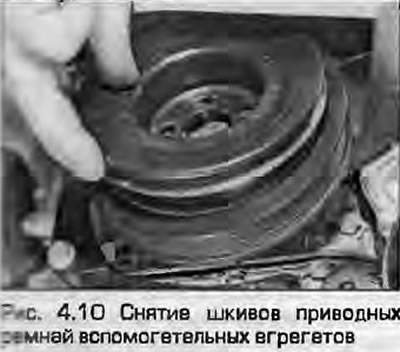
10. Loosen the mounting screws and remove the auxiliary belt pulley (if installed, together with the air conditioning compressor pulley) from the crankshaft sprocket (Fig. 4.10). Make sure that the engine TDC marks are aligned.
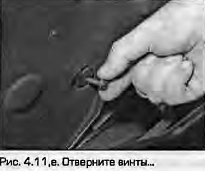
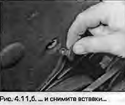
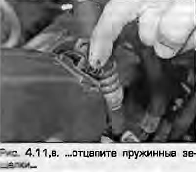
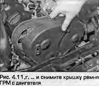
11. Release the upper part of the timing belt cover by unhooking the metal latches and, if necessary, unscrew the screws and remove the inserts (Fig. 4.11). Remove the cover from the engine.
 |
 |
 |
 |
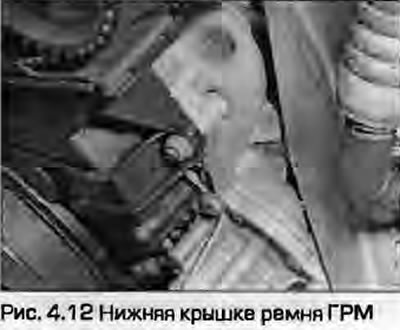
12. Loosen the bolts and remove the lower outer timing belt cover from the cylinder block (Fig. 4.12).
13. As described in paragraph 5, relieve the timing belt tension by slightly loosening the tensioner mounting nut so that it can be moved away from the belt.
14. Find the manufacturer's mark on the belt indicating the direction of rotation of the belt. If there is no mark, apply your own with paint or a marker - do not scratch the belt.
Warning: If the belt is to be reinstalled, install it observing the direction of rotation mark, otherwise wear will progress, leading to rapid and serious engine failure.
15. Pull the timing belt off all sprockets and remove the belt from the engine. If you are reinstalling the belt, DO NOT bend it too much.
Examination
16. Check the timing belt carefully for wear, delamination, cracks or decomposition of its material from oil. If traces of oil on the belt are found, find the cause and eliminate it, wash off all traces of oil around the belt installation area. If there is even the slightest doubt about the suitability of the belt, its replacement will be much cheaper than a potential engine repair. The belt is replaced every 60,000 km, however, if the car's mileage is less, the belt should also be replaced as a preventive measure.
17. If the belt is removed for a long time, hang a warning sign on the steering wheel to prevent the engine from accidentally starting or cranking.
18. On ANN engines, the bolts securing the fuel injection pump sprocket to the hub must be replaced after they have become loose. Purchase three new bolts before installing the belt. The bolts stretch when tightened to the prescribed angles - they cannot be used again. Audi requires that the injection timing MUST be adjusted after replacing the belt - simply installing a new belt using the marks is not sufficient.
Installation
19. Make sure that the crankshaft and camshaft are set to the TDC position of the compression stroke of the first cylinder, as described in paragraph 2.
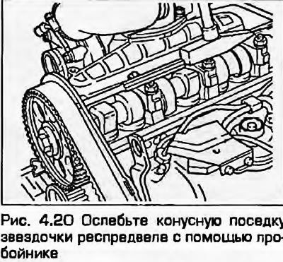
20. As described in paragraph 5, loosen the camshaft sprocket mounting bolt by 1/2 turn. Do not use the camshaft locking bar to hold the camshaft still - it can be bent; the bar must be removed before loosening the bolt. Release the sprocket's tapered fit by inserting a punch into the hole in the rear timing belt cover and tapping the rear side of the sprocket with a hammer through the punch (Fig. 4.20).
21. On ANN engines, unscrew the three bolts securing the fuel injection pump sprocket and screw in new ones (see item 18), tightening them at this stage "by hand" (Fig. 4.21). Install the outer sprocket in the center of the oblong holes.
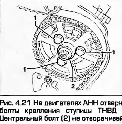
Warning: Do not loosen the center nut or the basic installation of the injection pump may be affected, requiring assistance from your Audi/VW dealer or a diesel specialist.
22. Locate the timing belt under the crankshaft sprocket.
Note: Make sure the belt rotation direction mark is correctly positioned.
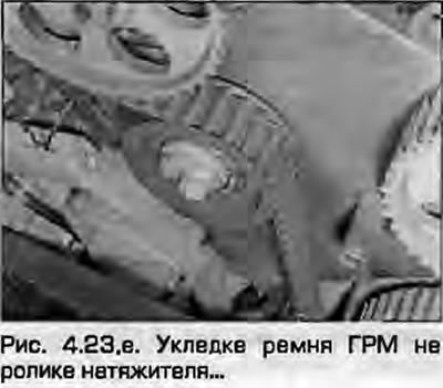
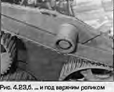
23. Align the belt teeth with the crankshaft sprocket, pass it around the auxiliary shaft sprocket, fuel pump sprocket, camshaft sprocket and tensioner pulley. Make sure the belt teeth match the sprockets. The upper shoulder of the belt should pass under the small upper roller.
Note: This may require slight adjustment of the camshaft sprocket position. Avoid excessive bending of the belt when installing it (fig. 4.23, a, b).
 |
 |
24. All belt slack should be on the tensioner roller side.
25. Insert the tensioner roller into the holes in the hub with pointed pliers with bent fingers and turn the tensioner pulley clockwise until the projections on the pulley and hub align (Fig. 4.25). The tensioners are of the semi-automatic type; when these projections are aligned, the correct belt tension will be ensured.
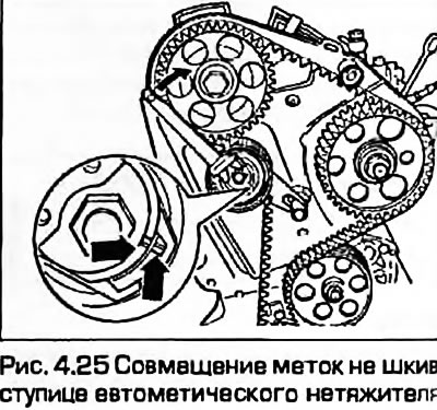
Note: If the tensioner is turned too far clockwise, it will have to be completely loosened before the belt can be tensioned again.
26. After aligning the tensioner marks, tighten the nut to the specified torque. Check the tensioner's functionality by pressing on the belt with your thumb and checking the divergence of the marks on the hub and the tensioner housing - after releasing the belt, the marks should match again.
27. Remove the locking pin from the fuel injection pump sprocket (see paragraph 2).
28. Remove the camshaft retaining plate (see paragraph 2).
29. On ANN engines, tighten the new fuel injection pump sprocket mounting bolts to an initial torque of 20 Nm, holding the outer sprocket from turning with a suitable tool. Do not knock the installation between the sprocket sections off. The final tightening of the bolts should be done after setting the injection torque of the fuel injection pump.
30. Check the installation of the camshaft and crankshaft at TDC (see paragraph 2). On ANN engines, if the locking pin cannot be inserted, temporarily loosen the three sprocket mounting bolts, move the sprocket as necessary and re-tighten the bolts to 20 Nm.
31. As described in paragraph 5, tighten the camshaft sprocket mounting bolt to the specified torque, holding it with a special tool to prevent it from turning.
32. Using a socket and a ratchet, grasp the central bolt securing the crankshaft sprocket and turn the crankshaft two full revolutions. Set the engine again to TDC of the first cylinder, as described in paragraph 2. Make sure that it is possible to insert the locking pin into the holes of the fuel injection pump sprocket and the bracket.
33. Install the valve cover together with a new gasket, - see paragraph 7.
34. Install the lower timing belt cover and secure it with latches and screws. Install the upper cover and secure it with all fasteners.
35. Install the auxiliary shaft pulley and tighten its mounting screws to the specified torque. Note that the asymmetrical arrangement of the bolt holes allows the pulley to be installed in only one position.
36. Install the boost pressure control solenoid valve and small cover to the right of the timing cover. Tighten the bolts.
37. Install the fan viscous coupling as described in chapter 3.
38. Install the tensioner on the front wall of the engine and install the accessory belts as described in paragraph 6.
39. Install the hood lock bracket in the reverse order of removal.
40. Install the lower powertrain guard and lower the vehicle. Install the upper engine cover.
41. Connect the negative cable to the battery as described in chapter 5A.
42. Finally, as described in chapter 4B, check the injection timing of the high-pressure fuel pump.
43. On ANN engines, remove the upper timing belt cover and tighten the fuel injection pump sprocket mounting bolts to the angles specified Specifications. Finally, install the top engine cover.
(A link to the original source is available on the website: AudiManual)