
Table of contents: Removal ↓ Removal and assembling manifolds ↓ Preparing for installation ↓ Installation ↓
Note: Disassembly and repair of the cylinder head are described in chapter 2B.
Removal
1. Before starting work, disconnect the negative battery cable as described in chapter 5A.
2. Drain the engine oil as described in chapter 1B.
3. Drain the coolant as described in chapter 1B.
4. Remove the auxiliary belts as described in paragraph 6. To do this, you will have to move the entire front panel away from the car to provide enough working space.
5. On models with air conditioning, loosen the tensioner bolts and move the tensioner pulley up to relieve tension on the drive belt. Remove the belt from the crankshaft pulleys, compressor and tensioner. Remove the air conditioning compressor from its mounting bracket and tie it aside without disconnecting the refrigerant lines.
6. Remove the fan viscous coupling as described in paragraph 5 of chapter 3. To do this, you can insert a hex key from behind, holding the assembly still with a fork-shaped tool secured in the pulley holes. If the Audi tool is not available, make a homemade one from two strips of metal, securing bolts in the ends of the "fork" to align with the pulley holes.
7. Remove the air filter as described in chapter 4B.
8. Disconnect the hose from the turbocharger pressure unit on the right side of the engine.
9. Remove the bolts securing the turbine to the catalytic converter. Release the front exhaust clamp and move it back, disconnect the downpipe and catalytic converter from the turbocharger.
Note: Be careful not to damage the flexible pipe of the exhaust system.
10. Loosen the clamps and remove the right air intake duct leading from the air cleaner to the turbocharger.
11. If installed, remove the turbine support brackets.
12. Loosen the connecting bolt and disconnect the return oil pipe from the cylinder block.
13. Loosen the clamp and carefully disconnect the upper hose on the left side of the cylinder head. Then disconnect the small bleeder hose from the top of the expansion tank. Move the hose to the side.
14. Loosen the nuts and remove the fuel pipes to the injectors (all at once).
15. Disconnect the wiring from the glow plugs.
16. Loosen the clamp and disconnect the cooling hose from the lower left side of the cylinder head.
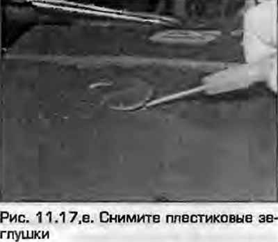
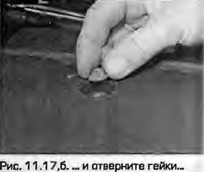
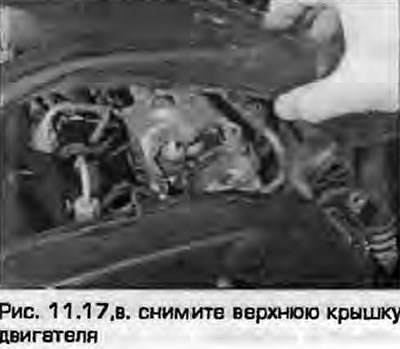
17. Remove the top cover and remove the valve cover as described in paragraph 7 (fig. 11.17).
 |
 |
18. Set the engine to TDC as described in paragraph 2.
19. Remove the timing belt tensioner, fuel injection pump sprockets and camshaft as described in paragraph 5.
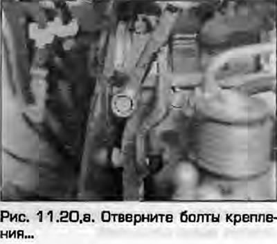
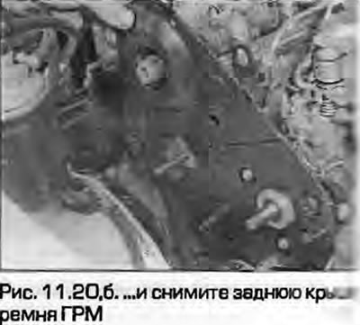
20. Remove the rear timing belt cover from the cylinder block (fig. 11.20, a, b).
 |
 |
21. Remove the air intake pipe installed at the rear of the engine. To do this, loosen the clamps and disconnect the short hoses from the turbine and intake manifold, disconnect the hoses and wiring and remove the pipe.
22. Remove the timing belt as described in paragraph 4. Remove the camshaft sprocket as described in paragraph 5.
23. Loosen the union nut, disconnect the oil feed pipe from the turbine.
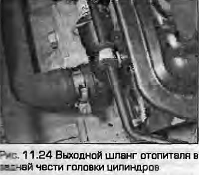
24. Loosen the clamp and disconnect the heater outlet hose from the flange at the rear of the cylinder head (fig. 11.24).
25. If necessary, disconnect the gasket from the three heater elements on the flange at the rear of the cylinder head.
26. Disconnect the return fuel hose from the injectors.
27. At the front of the cylinder head, disconnect the wiring secured to the upper cover bracket.
28. In the reverse order of tightening (see Fig. 11.57, a), gradually loosen the cylinder head mounting bolts by half a turn per pass until all the bolts can be unscrewed "by hand". Discard the bolts - new ones will be required for installation.
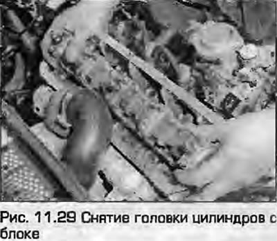
29. Once again, make sure everything is disconnected from the head and set aside. Remove the head from the cylinder block. If necessary, ask an assistant to assist, as the head is quite heavy, especially if removed together with the manifolds (fig. 11.29).
30. Remove the gasket from the block, following the guide bushings. If the bushings are loose, remove them and fold them so as not to lose them. Do not throw away the gasket yet - you will need it to identify the new one.
31. If the head needs to be disassembled for repair, refer to the description chapters 2B.
Removal and assembling manifolds
32. With the head on the workbench, remove the turbocharger as described in chapter 4B.
33. Remove the EGR valve as described in chapter 4B.
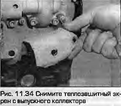
34. On AZ, AFF and AHU engines, remove the nuts and small heat shields from the front of the exhaust manifold (fig. 11.34).
35. Gradually loosen the mounting bolts and remove the intake manifold from the head. Remove the gasket and discard it.
36. If necessary, remove the oil feed pipe and bracket from the exhaust manifold.
37. Gradually loosen the mounting nuts and remove the exhaust manifold from the cylinder head. Remove the gaskets and discard them. Discard the self-locking nuts (with filler) and buy new ones.
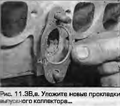
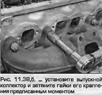
38. Clean the mating surfaces of both manifolds. Install the exhaust manifold with new gaskets and nuts. Place the gaskets correctly so that they do not damage the intake manifold gasket. Tighten the exhaust manifold mounting nuts to the specified torque - see chapter 4B (fig. 11.30).
 |
 |
39. If necessary, connect the oil feed pipe to the outlet manifold and tighten the bolt.
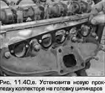
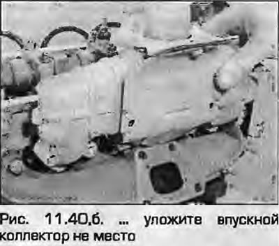
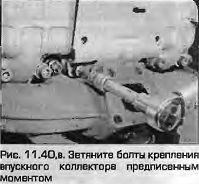
40. Install a new intake manifold gasket and reinstall the manifold. Install the mounting bolts and tighten them to the specified torque as described in chapter 4B (fig. 11.40, a, b).
 |
 |
41. Install the heat shield onto the exhaust manifold studs, tighten the mounting nuts and tighten.
42. Install the EGR valve as described chapter 4B.
43. Install the turbocharger to the intake and exhaust manifolds - see. chapter 4B.
Preparing for installation
44. Before installation, the mating surfaces of the head and cylinder block must be completely clean. Use a hard plastic or wooden scraper to remove all traces of the old gasket and carbon deposits. Also clean the piston crowns. Be extremely careful - the surfaces are easy to damage. Remember that dirt should not get into the oil and water channels and threaded holes for bolts - plug them with plugs or seal them with adhesive tape. To prevent carbon deposits from getting into the gap between the pistons and cylinders, apply a layer of thick grease to the gap - the grease after cleaning can be easily removed with a stiff brush. After cleaning, wipe everything with a clean dry rag.
45. Inspect the mating surfaces of the head and block for deep scratches, cracks and other damage. Minor defects can be removed with a fine scraper, but serious ones may require replacement of the head, since grinding the head is unacceptable - refer to the description chapters 2B.
46. If there is a suspicion that the head is warped, check the mating plane of the head with a steel ruler as described in chapter 2B.
47. Tap the block threads for the head bolts. If you don't have one, make your own.
48. On the engines discussed in this chapter, if the timing belt is removed, the crankshaft is set to TDC and the camshaft is rotated, the pistons will hit the valves. Therefore, the camshaft must be locked at TDC when installing the head on the block by inserting a locking film into the slot in the heel of the camshaft. The crankshaft must also be set to TDC of the first cylinder before installing the head.
Installation
49. Find the thickness markings on the old gasket. These should be either notches or holes and a catalog number. If you are not installing new pistons, the gasket must be installed with the same thickness.
50. If new pistons are installed, how to obtain a new gasket - calculate its thickness by measuring the piston protrusion as described in chapter 2B.
51. Place the new gasket on the block, aligning it with the guide bushings. Make sure that the TOP inscription and the manufacturer's catalog number are on top.
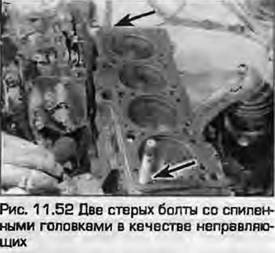
52. Cut off the heads of two old cylinder head mounting bolts. Saw a slot for a screwdriver. This will create convenient guides for installation in the heads (fig. 11.52).
53. Together with an assistant, place the head with the manifolds on the cylinder block, aligning it with the guide bushings.
54. Unscrew the homemade guides.
55. Lubricate the threaded parts and the undersides of the heads of the new bolts.
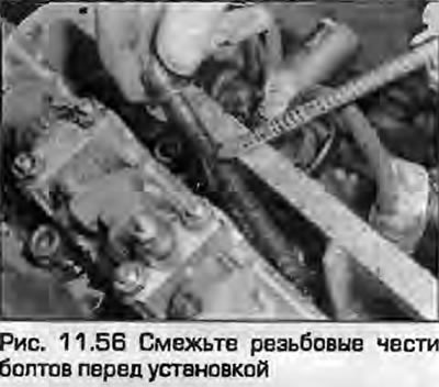
56. Carefully lower one bolt at a time into the holes (don't drop them) and at this stage, wrap them "by hand" (fig. 11.56).
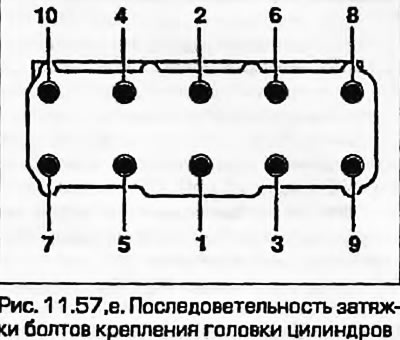
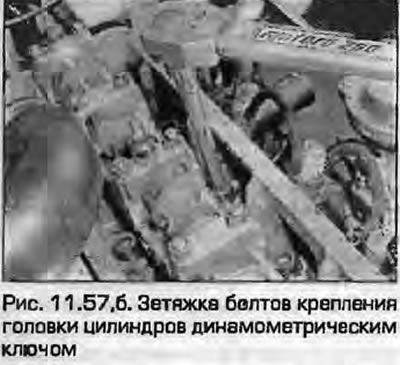
57. Working gradually in the sequence shown, tighten the head bolts to the specified torque Specifications stages using a torque wrench with a suitable socket (fig. 11.57). Repeat this exercise in the same sequence for stage 2.
 |
 |
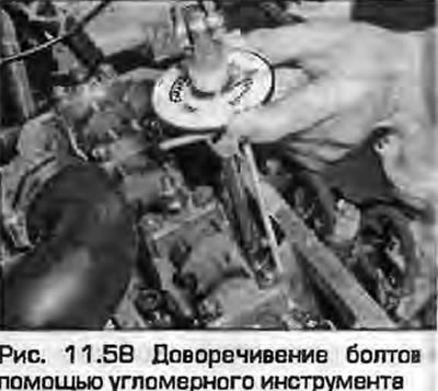
58. After all bolts have been tightened to stage 2, again in the sequence shown, tighten all bolts to the prescribed torque Specifications angle in the stage using a goniometer attachment on the handle. If there is no goniometer attachment, before tightening the bolts, apply white paint to the angle marks to comply with the requirements Specifications. Then tighten all the bolts to the corners prescribed up to stage 4 (fig. 11.58).
Note: The head bolts do not require tightening to start.
59. As described in paragraph 2, make sure that the TDC marks match.
60. The rest of the procedure is the reverse of removal. Finally, do the following:
- a) Fill the cooling system with the prescribed type and quantity of fluid as described in chapter 1B.
- b) Fill the engine with the prescribed type and quantity of oil as described in chapter 1B.
[This article was copied from the website AUDIMANUAL.RU]