
Table of contents: Removal ↓ Installation ↓
Removal
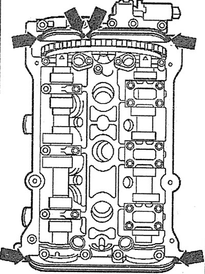
1. Remove the battery cover (see arrows in the illustration). If a protective cover is not provided, remove the fairing.
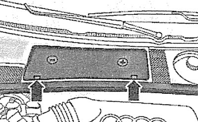
4.1 Remove the battery cover (see arrows)
2. Disconnect the negative (-) battery terminal from the battery (see arrow in illustration).
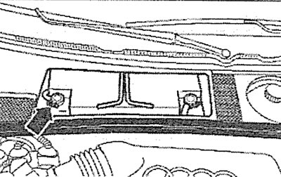
4.2. Disconnect the negative (-) battery terminal from the battery (see arrow)
3. Remove the front bumper (see the relevant chapter).
4. Set the upper front cross member to the service position (see section 2C, paragraphs 3.1-3.6).
5. Drain the coolant.
6. Disconnect the inlet pipe from the exhaust manifold.
7. Vehicles with afterburning system. Left cylinder head. Unscrew bolts 1 fresh air intake valve to exhaust valves (see illustration).
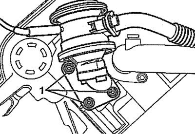
4.7. Unscrew bolts 1 of the fresh air intake valve to the exhaust valves. Left cylinder head. Cars with an afterburning system
8. Remove the timing belt of the gas distribution mechanism drive (see the relevant chapter).
9. Remove the camshaft gear.
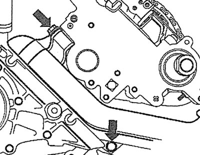
10. Unscrew the mounting bolts (see arrows in illustrations 4.10 and 4.10a) and remove the left/right parts of the rear timing cover.
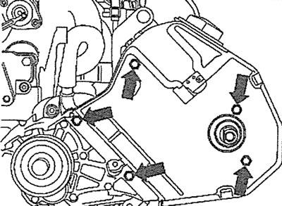
4.10. Unscrew the mounting bolts (see arrows) and remove the left side of the rear timing cover |
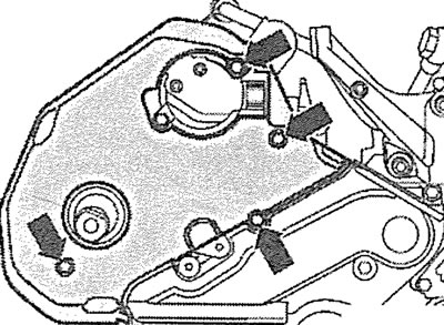
4.10a. Unscrew the mounting bolts (see arrows) and remove the right side of the rear timing cover |
11. Remove the intake manifold (see the relevant chapter).
12. Left cylinder head. Disconnect the crankcase ventilation hose (see arrows in the illustration).
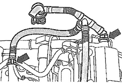
4.12. Disconnect the crankcase ventilation hose (see arrows). Left cylinder head
13. Disconnect the camshaft position sensor plug (hall sensor a), as well as the plug of the camshaft position adjuster valve.
14. Cars with afterburning system. Left cylinder head. Disconnect coolant hose 3, then disconnect low pressure hose 1 from fresh air intake valve to exhaust valves, unscrew connecting nipple 4, unscrew bolts 2 and remove valve, unscrew bolt 5 (see illustration).
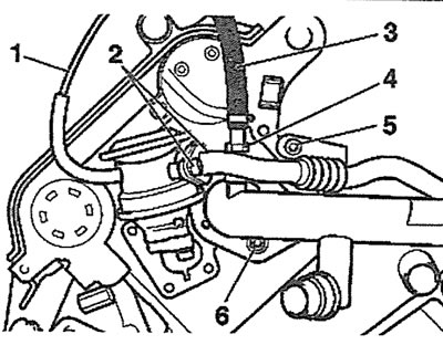
4.14. Disconnect coolant hose 3, then disconnect low pressure hose 1 from fresh air intake valve to exhaust valves, unscrew connecting nipple 4, unscrew bolts 2 and remove valve, unscrew bolt 5. Left cylinder head. Cars with afterburning system
15. Vehicles with afterburning system. Right cylinder head. Disconnect the low pressure hose 4 from the fresh air intake valve to the exhaust valves, then unscrew the bolts 3, as well as the bolt 1 of the connecting pipe holder (see illustration).
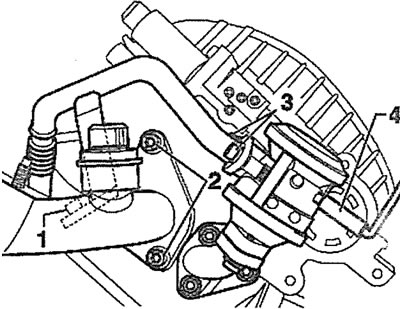
4.15. Disconnect low pressure hose 4 from the fresh air intake valve to the exhaust valves, then unscrew bolts 3 and also bolt 1 of the connecting pipe holder. Right cylinder head. Cars with afterburning system
16. Unscrew two bolts 6 (see illustration 4.14) or two bolts 2 (see illustration 4.15) coolant pipe holder. It is not necessary to completely disconnect the pipe.
17. Left cylinder head. Unscrew the bolts (see arrows in the illustration) fasteners and disconnect the cooling system pipe from the cylinder head.
4.17. Unscrew the bolts (see arrows) fasteners and disconnect the coolant pipe from the cylinder head. Left cylinder head
18. Right cylinder head. Disconnect the pressure line from the power steering pump and the cylinder head cover (see arrows in the illustration).
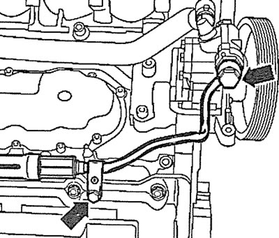
4.18. Disconnect the pressure line from the power steering pump and the cylinder head cover (see arrows). Right cylinder head
19. Unscrew the mounting bolts and remove the cylinder head cover.
20. Loosen the tightening and then completely unscrew the cylinder head mounting bolts in the sequence shown in the illustration.
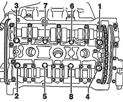
4.20. Loosen the tightening and then completely unscrew the cylinder head mounting bolts in the specified sequence
Installation
The cylinder head is installed in the reverse order of removal.
21. Check the condition of the cylinder head and make sure there are no cracks or dents.
22. Clean the threads of the cylinder head bolt holes. There should be no oil or other contaminants in these holes. If necessary, blow out the holes with compressed air or clean them with a screwdriver wrapped in a rag that absorbs liquid. Oil can be collected from the holes with a grease gun. If this is not done, then when screwing in the bolts, excess pressure will be created in the holes, which can lead to a rupture of the cylinder block or incorrect tightening torque of the bolts.
23. Remove the remains of the old seal from the surface of the cylinder block and head using a plastic scraper. Do not allow dirt and seal remains to get into the cylinder bores. Cover the cylinder bores with a rag.
Attention! Cleaning the sealing surfaces with a metal brush or other metal tool is not permitted.
24. Check the cylinder head for warpage, deformation or distortion using a feeler gauge and a steel ruler (see illustration). The maximum permissible head warpage should not exceed 0.1 mm. Cylinder head modification is allowed up to the minimum dimension "a", which is 139.25 mm (see illustration 4.24a).
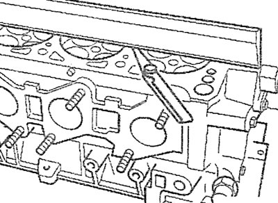
4.24. Check the cylinder head for distortion, deformation or warping using a feeler gauge and a steel ruler |
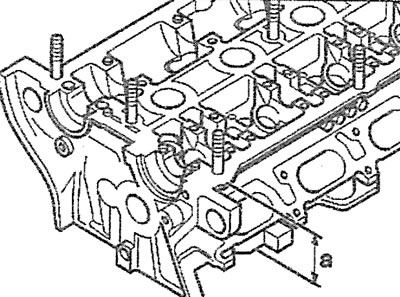
4.24a. Modification of the cylinder head is permitted up to the minimum dimension "a", which is 139.25 mm |
25. Before installing the cylinder head, make sure that both large diameter holes on the camshaft gear mounting plates are (see arrows in illustration 4.25) facing inwards and the crankshaft is locked with locking pin 3242 (see illustration 4.25a).
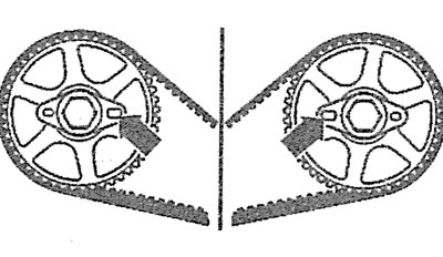
4.25. Ensure that both large diameter holes on the camshaft gear mounting plates are (see arrows) turned inward |
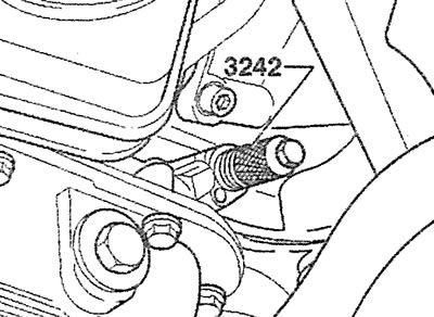
4.25a. Make sure that the crankshaft is locked with the locking pin 3242 |
26. Inspect the removed cylinder head gasket and, if the pistons, connecting rods or crankshaft have not been replaced, install a new gasket of the same thickness as the old one. The "Oben/Top" marking on the gasket must face upwards, towards the cylinder head, when installing it.
27. Make sure the locating pins are positioned correctly (see arrows in the illustration).
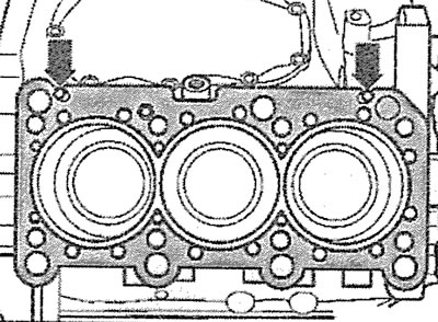
4.27. Make sure the dowel pins are positioned correctly (see arrows)
28. The new cylinder head being purchased can be installed on either the right or left cylinder block. The hole on the end face of the head should be plugged. To do this, apply sealant to the mating surface of the plug, and then install the plug into the hole using a suitable mandrel, such as a mandrel with catalog number 295 (see illustration).
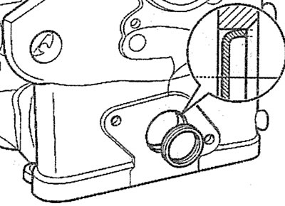
4.28. Install the plug into the hole on the end face of the cylinder head using a suitable drift
29. Apply a small amount of sealant to the areas indicated by the arrows in the illustration.
4.29. Apply a small amount of sealant to the areas indicated by the arrows
30. Tighten the cylinder head bolts in several passes in the sequence shown in the illustration:
- 1st pass - tighten the bolts to 60 Nm;
- 2nd pass - tighten the bolts by 90°;
- 3rd pass - tighten the bolts 90° further.
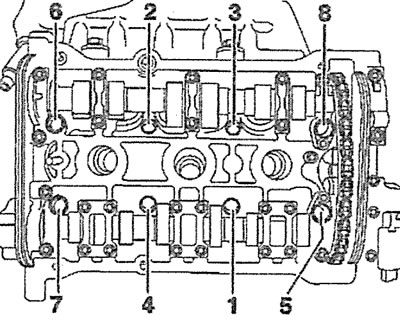
4.30. Tighten the cylinder head bolts in several passes in the sequence shown
The article is a reprint of material from: AUDImanual.ru