
Table of contents: Removal ↓ Installation ↓
Removal
1. Remove the front bumper (see the relevant chapter).
2. Set the upper front cross member to the service position.
3. Unscrew the radiator fan with a viscous coupling, holding its hub from turning with a second wrench, then remove the diffuser.
4. Remove the accessory drive V-belt (see the relevant chapter).
5. Unscrew the bolt (see arrow in illustration) and remove the tension roller of the auxiliary drive V-belt.
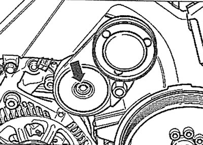
2.5. Unscrew the bolt (see arrow) and remove the tension roller of the auxiliary drive V-belt
6. Cars with afterburning system. Disconnect the hose (see arrow in illustration) from the fresh air supply pump to the outlet valves.
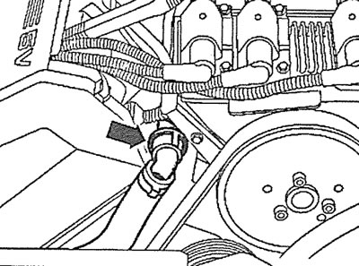
2.6. Disconnect the hose (see arrow) from the fresh air supply pump to the exhaust valves. Cars with afterburning system
7. Unscrew the mounting bolts and remove the right and left parts of the rear timing cover.
8. Set the piston of cylinder No.1 to TDC by turning the crankshaft in the direction of engine rotation by the central bolt securing the drive gear until mark B on the belt pulley aligns with mark A on the timing cover (see illustration).
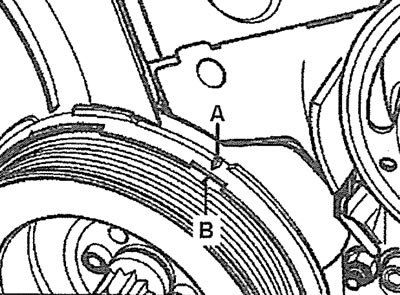
2.8. Turn the crankshaft in the direction of engine rotation using the central bolt securing the drive gear until mark B on the belt pulley aligns with mark A on the timing gear cover
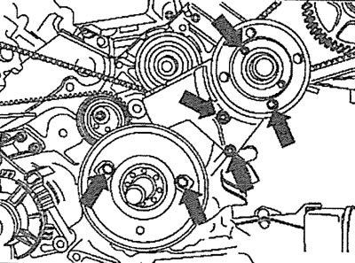
9. Make sure that the large diameter holes of the camshaft gear mounting plates are on the inside opposite each other (see arrows in the illustration). Otherwise, turn the crankshaft in the direction of engine rotation one more revolution.
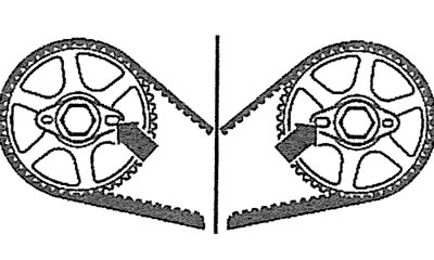
2.9. Make sure that the large diameter holes of the camshaft gear mounting plates are on the inside opposite each other (see arrows)
10. Cars with parking heater. Unscrew the bolts (see arrows in the illustration) fastening the heater pipe to the soundproofing shield.
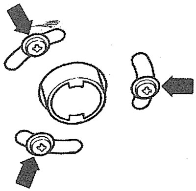
2.10. Unscrew the bolts (see arrows) fastening the heater pipe to the soundproofing shield. Cars with a parking heater
11. Unscrew the mounting bolts (see arrows in the illustration) and remove the engine splash guard.
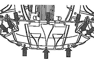
2.11. Unscrew the mounting bolts (see arrows) and remove the engine splash guard
12. Unscrew the threaded plug on the cylinder block at approximately the level of the middle cylinder.
13. Screw in the locking pin instead of the plug, catalog number 3242 (see illustration). Make sure that the pin enters the hole in the crankshaft cheek and locks the shaft.

2.13. Screw in the locking pin instead of the plug, catalog number 3242
14. Unscrew the mounting bolts and remove the vibration damper.
15. Unscrew the bolts (see arrows in the illustration) fasteners and remove the lower part of the timing drive protective cover and the radiator fan pulley with a viscous coupling.
2.15. Unscrew the bolts (see arrows) fasteners and remove the lower part of the protective cover of the timing drive and the pulley of the radiator blower fan with a viscous coupling
16. Unscrew the camshaft gear mounting bolts, holding the gears from turning with a tool, catalog number 3036 (see illustration).
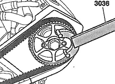
2.16. Unscrew the camshaft gear mounting bolts, holding the gears from turning with a tool, catalog number 3036
17.. Remove the camshaft gears using a puller, catalog number T40001 (see illustration).
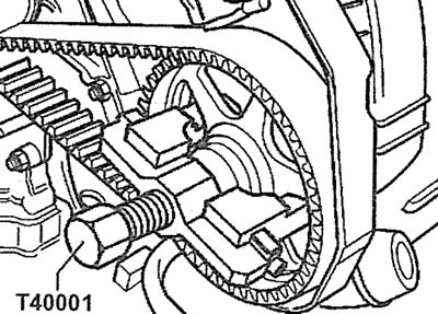
2.17. Remove the camshaft gears using a puller, catalog number T40001
18. Mark the direction of rotation of the timing belt with chalk, marker or paint if the belt is to be reinstalled. Failure to maintain the previous direction of rotation of the timing belt during its further use may result in its damage or rupture.
Caution! The timing belt tensioner plunger has an oil-filled shock absorber and therefore its compression is performed slowly with the application of uniform force. Excessive force when compressing the tensioner can lead to damage to the tension roller.
19. Loosen the timing belt tension by inserting a socket wrench into the hex hole in the tension roller and turning the roller in the direction indicated by the arrow in the illustration until the holes in the plunger and tensioner housing align. Insert the T40011 thrust pin into the aligned holes, thereby securing the plunger in the tensioner housing (see illustration).
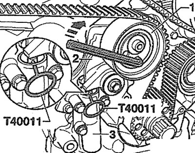
2.19. Insert the socket wrench into the hex hole of the tension roller and turn the roller (see arrow), until the holes on the plunger and the tensioner body are aligned. Insert the T40011 thrust pin into the aligned holes, thereby securing the plunger in the tensioner body:
1 - tension roller
2 - tensioner lever
3 - tensioner housing
20. Carefully remove the timing belt.
Installation
Caution! The toothed belt must not be bent, twisted or rolled up. A dirty, damaged or worn belt must be replaced.
Caution! Do not turn the crankshaft or camshafts with the timing belt removed. If it is necessary to change the position of the camshaft after removing the timing belt, make sure that the crankshaft is not in the position corresponding to the TDC of the piston of cylinder No.1 to avoid the valves hitting the piston crowns. Then mark the position of the timing drive pinion on the crankshaft by applying paint marks to the pinion itself and the cylinder block. Then turn the pinion 1/4 turn (90°) forward or backward.
21. Make sure that the crankshaft is secured with the locking pin, part number 3242 (see illustration 2.13).
22. Install the camshaft gears, secure them with bolts and mounting plates so that the gears can be turned on the hubs.
Attention! The mounting plates have markings "front" (front side), "rear" (back side). Follow the markings when installing the plates.
23. Install the timing belt, keeping its previous direction of rotation (see illustration). Lastly, place the timing belt on the tension roller.
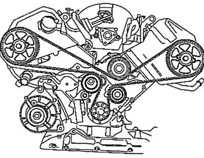
2.23. Direction of laying the timing belt of the gas distribution mechanism drive
24. Lock the camshafts with a locking tool, part number 3391 (see illustration).
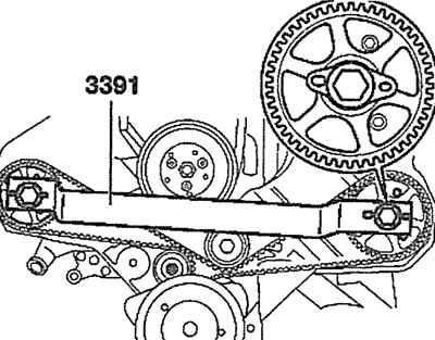
2.24. Lock the camshafts with a locking tool, part number 3391
25. Remove the T40011 thrust pin used to secure the plunger in the timing belt tensioner housing. To help release the pin from the aligned holes in the plunger and the tensioner housing, use a socket wrench to turn the tension roller in the direction indicated by the arrow in Illustration 2.13. The timing belt tensioner plunger will provide the required belt tension.
26. Tighten the tension roller to 15 Nm.
27. Tighten the camshaft gear mounting bolts to 30 Nm.
Next, the installation of the dismantled components is carried out in the reverse order of removal.
[Material republished from the website: AudiManual.ru]