
Table of contents: Additional electric fan ↓ Viscous coupling driven fan ↓
Additional electric fan
Examination
1. The power supply voltage to the fans is supplied via the ignition switch, fuse and a pair of series-connected (service) resistors. The circuit is completed by a fan switch sensor screwed into the left side of the radiator.
2. If it turns out that the fan refuses to work, warm up the engine to operating temperature and let it idle. After a few minutes, the fan should turn on (until the temperature indicator arrow reaches the red sector or until the warning indicator lights up).
3. If this does not happen, turn off the ignition and disconnect the test connector from the fan switch. Short-circuit the two contacts on the connector (see Electrical diagrams - most models have two-stage sensors) with a piece of wire and turn on the ignition. If the fan does not work, the sensor is probably burned out - in this case it is replaced.
4. If the fan still does not rotate, check for power supply voltage at the switch. If there is no voltage, check the entire circuit (the fault may be in the motor, and the fuse may burn out). If there is voltage, check the connection of the sensor's "ground" terminal to the "ground". The connection may need to be restored.
5. If both power and ground are present, the fan motor is most likely faulty. To check it, you can connect 12V power directly.
Removal
6. Remove the radiator as described in paragraph 3.
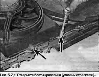
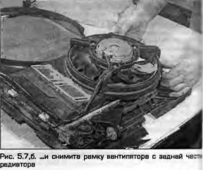
7. Loosen and remove the mounting bolts, remove the fan frame from the rear of the radiator (fig. 5.7, a, b).
 |
 |
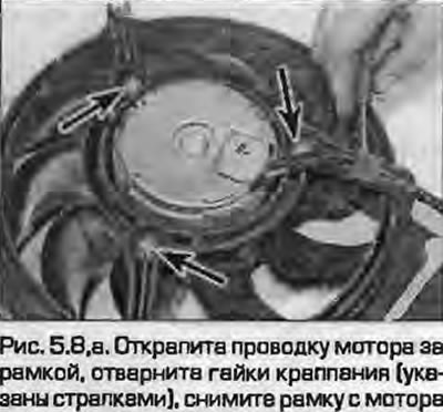
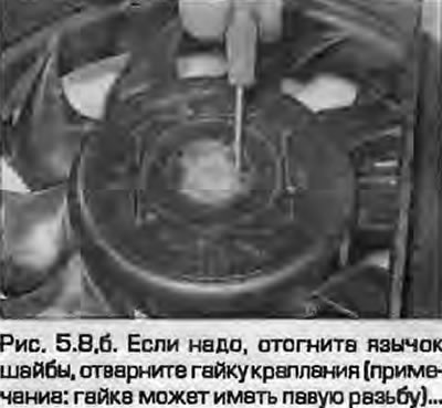
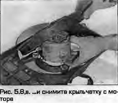
8. Unclip the motor wiring at the back of the frame, remove the mounting nuts and pull the motor out of the frame. On some models you may have to remove the impeller from the motor to allow enough clearance. Bend back the lock washer and remove the mounting nut (on some models the nut has a left-hand thread), to remove the impeller (fig. 5.8, a-c). If the motor is faulty, spare parts are not supplied for it, the motor is replaced entirely.
 |
 |
Installation
9. Install the fan on the frame and tighten the nuts securely. Lay the wiring correctly and attach it. If necessary, seat the impeller on the motor shaft, install the lock washer and tighten the nut. Tighten the nut and bend the tab of the lock washer.
10. Install the fan with the frame on the radiator and tighten the mounting bolts securely.
11. Install the radiator as described in paragraph 3.
Viscous coupling driven fan
Examination
12. For a car enthusiast, testing the operation of a viscous coupling may present certain difficulties. The only easy-to-do check is the absence of coupling leaks and the integrity of the blades. When the coupling is cold, the fan rotates freely, the coupling only operates at a temperature of 75°C. If there is any doubt about the coupling's performance, it is replaced.
Removal
Note: The Audi reed key part number 3212 or a suitable replacement is very useful for removing the coupling.
13. Move the front panel to the "service" position as described in chapter 11.
14. Remove the auxiliary drive belt as described in Chapter 2A or 2B.
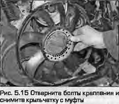
15. Loosen the mounting bolts and remove the impeller from the coupling, remembering the method of their installation (Fig. 5.15).
16. Lock the pulley with a 5x60 mm bolt by inserting it into any of the holes according to the pulley size. Pass an 8 mm Allen key through the drive pulley mounting bracket, insert it from the back into the head of the axle bolt. Loosen, unscrew the bolt, remove the viscous coupling from the engine (Fig. 5.16).
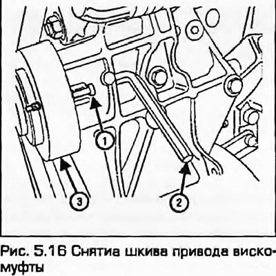
Fig. 5.16. Removing the viscous coupling drive pulley: 1. Bolt 5X60 mm; 2. Hexagon 8 mm; 3. Pulley
17. If necessary, the viscous coupling can be moved away from the pulley by unscrewing the mounting bolts.
Installation
18. Install the viscous coupling on the pulley (if it was filmed) and tighten the mounting bolts to the specified torque.
19. Install the pulley with the coupling in place, insert the axle bolt and tighten it to the specified torque. To do this, insert the hex key from the back of the coupling into the head of the axle bolt, locking the pulley with a 5x80 mm bolt inserted into one of the peripheral holes, as during removal.
20. Install the impeller.
21. Install the auxiliary drive belt as described in Chapter 2A or 2B.
22. Install the front panel as described in chapter 11.