
Table of contents: Early models 1.6 l (aHL petrol… ↓ All other petrol engines (except AHL) ↓ Diesel engines ↓
Early models 1.6 l (aHL petrol engine)
Removal
1. Disconnect the negative battery cable, drain the coolant as described in chapter 1A.
2. Move the front body panel to the service position - see chapter 11.
3. Remove the accessory drive belt as described in chapter 2A.
4. Remove the fan viscous coupling as described in paragraph 5.
5. As described in "Timing belt - removal, inspection and installation", remove the timing belt from the camshaft sprockets and water pump. There is no need to remove the belt from the crankshaft sprocket - the crankshaft pulley and lower belt cover may be in place.
6. Loosen the screws and remove the upper part of the rear timing belt cover.
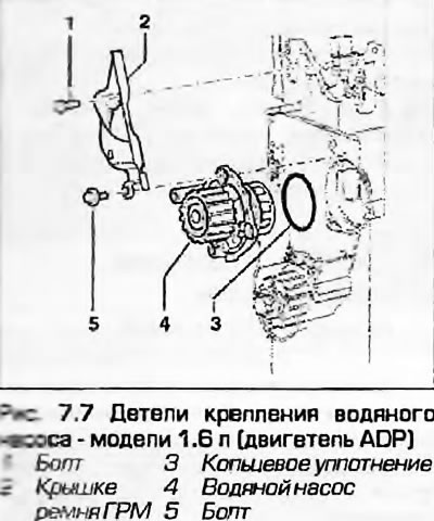
7. Unscrew the water pump mounting bolts. Remove the pump from the cylinder block and remove the sealing ring (Fig. 7.7).
Installation
8. First, thoroughly clean the pump seat in the block, removing all traces of old sealant.
9. Obtain a new O-ring and wet it with the prescribed type of antifreeze (see Recommended Fluids, Oils and Lubricants). Install the ring into its place in the block.
10. Install the pump into the block with the mounting protrusion facing down.
11. Tighten the mounting bolts gradually and evenly to the specified torque.
12. Install the rear timing belt cover. Install the timing belt - see chapter 2A.
13. Install the viscous coupling with the fan.
14. Install the front body panel as described in chapter 11 and tighten its mounting bolts to the specified torque.
15. Finally, fill the coolant as described in the relevant section chapters 1 and connect the battery.
All other petrol engines (except AHL)
Removal
16. Disconnect the ground cable from the battery and drain the coolant as described in chapter 1A.
17. Move the front body panel to the "service" position as described in chapter 11.
18. Remove the accessory drive belt as described in chapter 2A. On engines with air conditioning, there is no need to remove the compressor drive frame.
19. Remove the fan viscous coupling as described in paragraph 5.
20. Secure the power steering pump pulley by inserting a screwdriver into the pulley hole and resting it against the pump mounting bracket. Remove the outer section of the water pump pulley and remove the V-belt.
21. Loosen the clamps and disconnect the coolant hoses from the rear of the pump housing and thermostat housing.
22. Remove the generator as described in chapter 5A.
23. Remove the power steering pump from its mounting bracket as described in chapter 10. There is no need to remove the hydraulic tubes/hoses from the pump. Move the pump away from the bracket and tie it up so it doesn't get in the way.
24. Remove the bolts/nuts (what is installed) and remove the alternator and/or power steering pump brackets from the engine to gain access to the water pump housing.
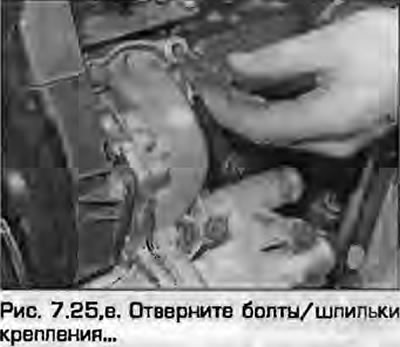
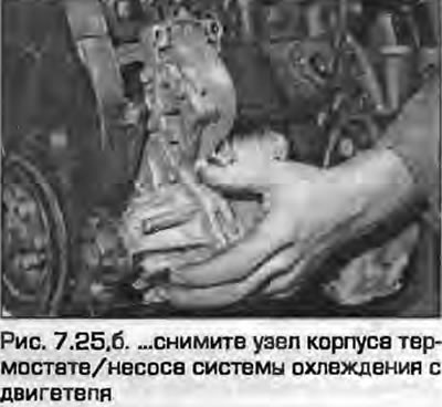
25. Loosen the bolts/studs securing the pump/thermostat housing to the block and remove the housing assembly from the engine.
Note: On some engines it will be necessary to remove the bolt securing the timing belt cover to the housing assembly (see chapter 2).
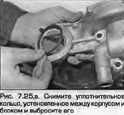
Remove the sealing ring installed between the housing and the block and discard it; new required for installation (fig. 7.25, a-c).
 |
 |
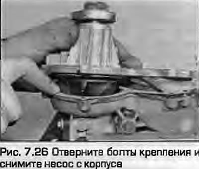
26. After installing the unit on the workbench, unscrew the mounting bolts and remove the pump from the housing (Fig. 7.26). Throw away the gasket - a new one is required for installation. The pump cannot be repaired, a faulty pump is always replaced. Remember to install the bolt with the sawn-off head.
Installation
27. Make sure the mating surfaces are clean. Apply a new gasket to the housing.
28. Install the pump onto the housing and tighten the bolts evenly to the specified torque. Install the sawn-off head bolt, which also secures the timing belt cover, before bolting the pump to the engine.
29. Install a new seal ring into the housing groove and install the housing into the cylinder block. Install the mounting studs/bolts and tighten them to the specified torque.
30. Carefully connect the cooling system hoses to the body and tighten the clamps securely.
31. Install the generator/power steering pump bracket and tighten the bolts/nut to the specified torque.
32. Assemble the two halves of the water pump pulley and place the V-belt on it. Fasten the pulley with the belt to the pump, tighten the mounting bolts and tighten them to the specified torque, turning the pulley by hand so as not to pinch the frame.
33. Install the power steering pump on the mounting bracket as described in chapter 10.
34. Install the generator as described in chapter 5A.
35. Install the main auxiliary belt as described in chapter 2A.
36. Install the viscous coupling with the fan as described in paragraph 5.
37. Install the front body panel as described in chapter 11.
38. Finally, fill the coolant as described in the relevant section chapters 1 and connect the generator.
Diesel engines
Removal
39. Disconnect the ground cable from the battery and drain the coolant as described in chapter 1B.
40. Move the front body panel to the "service" position.
41. Remove the main accessory drive frame - see chapter 2B. On medals with air conditioning, the compressor drive belt does not need to be removed.
42. Remove the fan viscous coupling as described in paragraph 5.
43. Lock the water pump pulley with a belt-type oil filter removal tool and remove the pulley from the water pump.
44. Unscrew the water pump mounting bolts. Carefully remove the pump from the block and remove the sealing ring (Fig. 7.44).
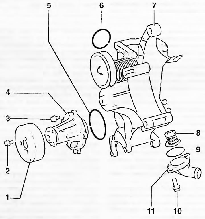
Fig. 7.44. Cooling system pump mounting parts - diesel engines: 1. Pulley hub; 2. Bolt; 3. Bolt; 4. Cooling system pump; 5. Sealing ring; 6. Sealing ring; 7. Body; 8. Thermostat; 9. Sealing ring; 10. Bolt; 11. Thermostat housing cover
Installation
45. Make sure the mating surfaces of the pump and block are clean, install a new sealing ring on the pump.
46. Tighten the pump mounting bolts gradually and evenly to the specified torque.
47. Install the main accessory drive belt as described in chapter 2B.
48. Install the viscous coupling with the fan as described in paragraph 5.
49. Install the front body panel as described in chapter 11.
50. Finally, fill the system with coolant as described in the relevant section chapters 1 and connect the battery.
(Content source: the specified website «AUDImanual.ru»)