
General information
1. The main purpose of the belt is to drive the camshaft. If the belt breaks or comes off while the engine is running, the valve timing will be disrupted, the pistons will hit the valves - there will be a serious breakdown. Therefore, it is very important for the belt to be properly tensioned. It is necessary to check the condition of the timing belt regularly.
Removal
2. Disconnect the battery by disconnecting its negative cable (see chapter 5A).
3. Apply the handbrake, raise the front of the vehicle and install safety stands. If necessary, remove the lower protective cover of the power unit.
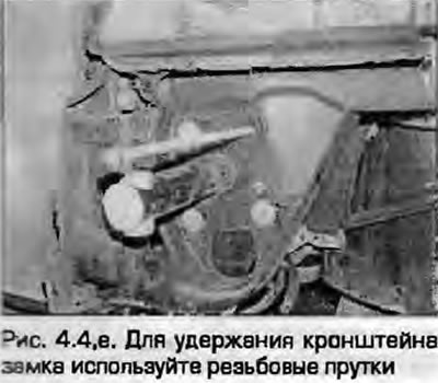
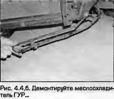
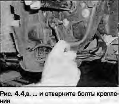
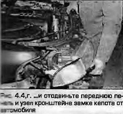
4. Access to the belt is possible after disconnecting the front body panel (together with the hood lock). Pull the panel away from the body as far as possible without disconnecting the wiring and radiator hoses. To do this, first remove the front bumper as described in chapter 11. disconnect the three quick-release fasteners of the noise-insulating panel, unscrew the bolts securing the air duct to the hood lock bracket and air filter. Remove the power steering oil cooler from the bottom of the radiator. Disconnect the wiring harness from the fasteners on the left side of the radiator. Unscrew the bolts securing the hood lock bracket assembly at the bottom of the body, unscrew the upper bolts, which are located behind the headlights. With the help of an assistant, remove the entire front panel assembly and move it away from the car as far as possible. To hold the panel, Audi mechanics usually use special template brackets, however, they can be made from a rod without cutting the threads on its ends. Screw these devices into the body side members (fig. 4.4, a-g).
 |
 |
 |
 |
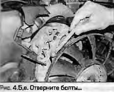
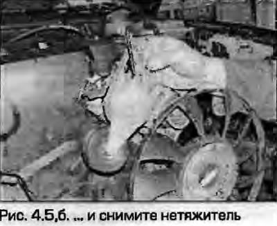
5. Remove the accessory drive belts as described in paragraph 6. Remove the tensioner from the front of the engine using an Allen key (fig. 4.5, a, b).
 |
 |
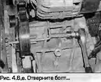
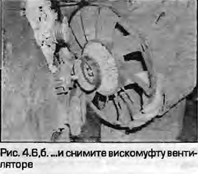
6. Remove the fan viscous coupling as described in paragraph 5 of Chapter 3. It is removed using a hex key from behind, holding it still with a bolt inserted from behind, resting against the cylinder block (fig. 4.6.a, b).
 |
 |
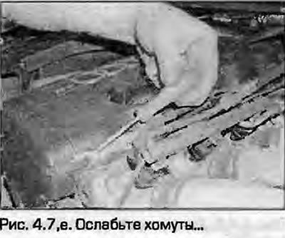
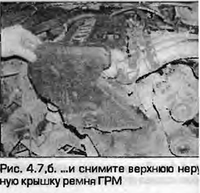
7. Unfasten and remove the upper outer timing belt cover (fig. 4.7, a, 6).
 |
 |
8. If the timing belt needs to be reinstalled, mark the direction of rotation on the back of the belt with a marker.
9. Set the engine to TDC as described in paragraph 2. Application: Make sure ALL TDC marks are aligned accurately, as the cam sprocket mark alone will not provide accuracy when installing the belt. If the cam sprocket mark is slightly out of alignment, apply a temporary second mark to use for installation.
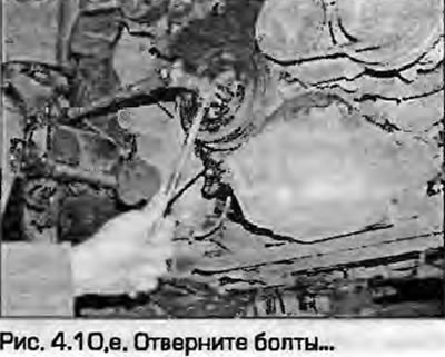
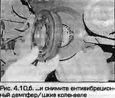
10. Holding the crankshaft still by the central pulley bolt with a socket and a ratchet, unscrew the pulley mounting bolts (or anti-vibration damper) to the crankshaft sprocket. Remove the pulley or damper (fig. 4.10, a, b).
 |
 |
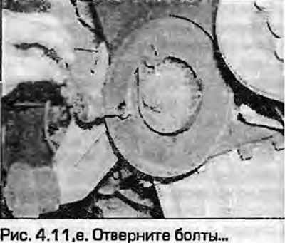
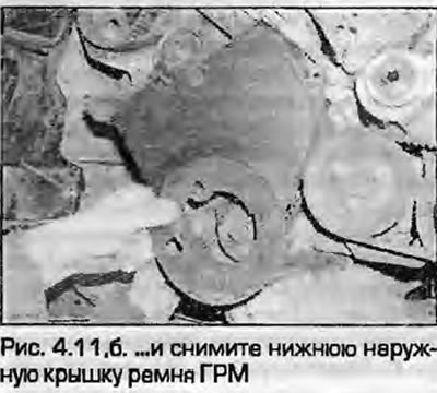
11. Loosen the bolts and remove the lower outer timing belt cover from the cylinder block (Fig. 4.11).
 |
 |
Engines ADP, ADR (up to 07/97). AFY (until 07/97), AEB, AJL, APT, APW
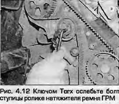
12. Using a Torx head, loosen the bolt securing the tensioner roller hub to the tensioner arm. Push the tensioner hub clockwise to release the timing belt tension (Fig. 4.12).
Engines ADR (from 08/97) and AFY (from 08/97)
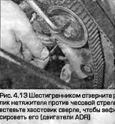
13. Insert a hex key into the tensioner hub hole and slowly turn the tensioner counterclockwise against the spring resistance. Align the small holes at the top of the tensioner and the inner cylinder, insert the shanks of a 2.0 mm drill bit to lock the tensioner in this position (Fig. 4.13). DO NOT loosen any tensioner bolts.
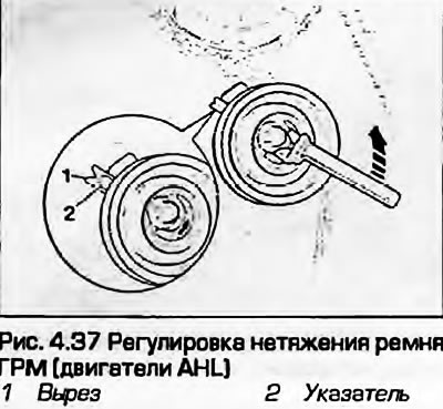
AHL engines
14. Loosen the central nut of the semi-automatic tensioner to completely release the belt tension.
All engines
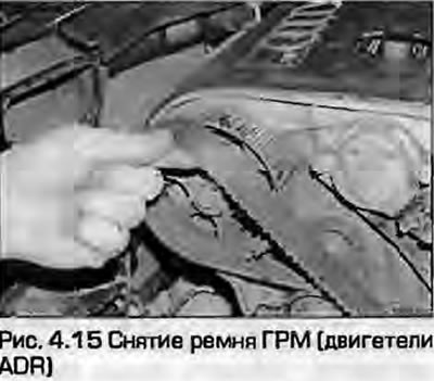
15. Pull the timing belt off all sprockets and remove the belt from the engine (Fig. 4.15). If you are going to reinstall the belt, DO NOT bend it too much.
Examination
16. Check the timing belt carefully for wear, delamination, cracks and decomposition of its material from the oil that has been applied. If traces of oil getting on the belt are found, find the cause and eliminate it, wash off all traces of oil around the belt installation area. If there is even the slightest doubt about the suitability of the belt, its replacement will be much cheaper than a potential engine repair. If the engine is being repaired, or has traveled more than 60,000 km since the last belt replacement, the belt is subject to replacement under any circumstances.
Note: If the belt is removed for a long time, attach a warning sign to the steering wheel to prevent the engine from accidentally starting or cranking.
Installation
Zzigetali ADP. ADR (until 07/97), AFY (until 07/97), AEB, AJL, APT, APW
17. Make sure that the TDC mark on the camshaft sprocket matches the corresponding mark on the valve cover, as described in paragraph 2.
18. Temporarily install the lower timing belt cover, install the pulley on the crankshaft sprocket, securing it with two mounting screws - note that the asymmetrical holes only allow the pulley to be installed in one position.
Note: The pulley mounting bolts have long threads - there is no need to tighten them all the way.
Make sure the marks match and remove the timing belt pulley and cover.
19. Trace the belt under the crankshaft sprocket. If the old belt is being installed, note the pre-marked direction of rotation.
20. On ADP engines, temporarily install the crankshaft pulley on the crankshaft sprocket and check that the marks on the crankshaft pulley and the auxiliary shaft sprocket match up. The mark on the crankshaft pulley should align with the dot on the auxiliary shaft sprocket. Note that the OT mark on the auxiliary shaft sprocket is not important. Check the position of the distributor rotor - it should point towards the contact in the cover intended for the first cylinder. After checking the marks, remove the pulley.
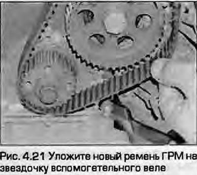
21. Align the belt teeth with the crankshaft sprocket teeth, place it on the auxiliary shaft sprocket and camshaft sprocket (fig. 44.21). Pay attention to the belt rotation direction mark.
22. Place the back of the belt around the tensioner pulley - do not bend the belt excessively. Take up the forward slack of the belt - the slack should be left on the tensioner pulley side.
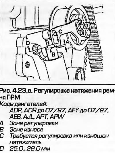
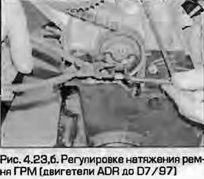
23. Tighten the belt by turning the tensioner hub counterclockwise and the spring-loaded lever clockwise; a hole and a projection are provided for this purpose. Instead of the specially provided VAG tool, you can use a pair of bent-nose pliers. Turn the tensioner until the spring-loaded inner piston protrudes completely, so that the outer piston protrudes by approximately 1.0 mm, then tighten the locking bolt. Check that the tooth "A" is aligned with the upper end of the outer piston (fig. 4.23,a, b). If necessary, loosen the locking bolt and adjust the tension again. The distance between the top of the outer piston and the top of the inner piston eye should be 25.0...29.0 mm.
 |
 |
Application: After installing a new timing belt, the eccentric hub will eventually (with belt stretching) will turn, bringing the top of the outer piston to position "B". If the outer piston ends up in position C, then the tensioner or belt is at its limit of wear.
24. On ADP engines, temporarily install the crankshaft pulley and check that the auxiliary shaft marks align with the mark on the pulley. Remove the pulley.
Engines ADR (from 08/97) and AFY (from 08/97)
25. Make sure that the mark on the camshaft sprocket is correctly aligned with the corresponding mark on the inner timing belt cover as described in paragraph 2. Trace the belt under the crankshaft sprocket, paying attention to the pre-applied mark for the direction of rotation of the belt if you are installing the old belt.
26. Temporarily place the lower timing belt cover and crankshaft pulley in place, securing it with a pair of bolts (asymmetrical holes allow the pulley to be installed in only one position).
27. Check the alignment of the marks on the pulley and cover. Since the auxiliary shaft does not drive anything except the oil pump, its position is not important.
28. Align the belt teeth with the crankshaft sprocket, place it around the auxiliary shaft and camshaft sprockets. Observe the correct direction of belt rotation - use the previously applied mark for this.
29. Place the belt with the back side on the tensioner pulley. Do not bend the belt too much. The front shoulder of the belt should be taut - the slack should be on the tensioner side 30. Using an 8.0 mm Allen key, turn the tensioner pulley counterclockwise, remove the drill and release the pulley so that the belt is taut.
AHL engines
31. Make sure that the mark on the crankshaft sprocket is aligned with the mark on the inner timing belt cover - see paragraph 2.
32. Loop the belt around the camshaft sprocket, observing the correct direction of rotation if the old belt is being installed.
33. Temporarily place the lower timing belt cover on and secure the crankshaft pulley to the sprocket with a pair of bolts, noting that the asymmetrical holes only allow the pulley to be installed in one position.
34. Check the alignment of the marks on the pulley and cover.
35. Align the belt teeth with the crankshaft sprocket, place it around the water pump and camshaft sprockets. Observe the belt rotation direction marks.
36. Place the back of the belt around the tensioner pulley - do not bend the belt too much. The front shoulder of the belt should be tight - the slack should be on the tensioner pulley side. The tongue at the base of the tensioner should align with the mark on the cylinder head.
37. Audi mechanics use a special tool that fits into two holes on the tensioner pulley. Alternatively, use a pair of needle-nose pliers bent at a right angle. Turn the tensioner counterclockwise as far as possible, then turn it slowly clockwise until the pointer is positioned 10.0 mm below the lug. Continue turning the tensioner until the two pointers are positioned opposite each other and in this position tighten the nut to the specified torque (Fig. 4.37).
All engines
38. Using a wrench or socket with a ratchet, turn the crankshaft two full revolutions by the central bolt securing the crankshaft sprocket. Set the piston of the first cylinder to TDC of the compression stroke - see paragraph 2 and make sure that the marks on the crankshaft pulley, auxiliary and camshaft sprockets are correctly aligned. Check the timing belt tension and adjust if necessary.
39. Install the lower part of the outer timing belt cover, install the crankshaft pulley. Tighten the pulley mounting bolts to the specified torque.
40. Install the upper part of the outer timing belt cover.
41. Install the fan viscous coupling as described in chapter 3, install the accessory drive belt tensioner and tighten the bolts. Install the accessory belts - see paragraph 6.
42. Install the hood lock bracket assembly in the reverse order of removal.
43. Install the lower powertrain guard and lower the vehicle.
44. Connect the battery as described in chapter 5A.
[The original version is on the portal: audimanual]