
Removal
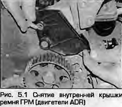
1. Remove the timing belt as described in paragraph 4. If necessary, remove the rear timing belt cover from the cylinder block (Fig. 5.1).
Tensioner/roller
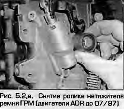
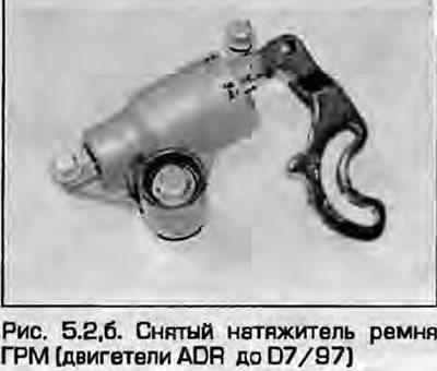
2. To remove the tensioner unit on ADP, ADR (up to 07/97), AFY (up to 07 97), AEB, AJL, APT, AP\N engines, unscrew the lower mounting bolt and the unit mounting bolt on the roller hub (Fig. 5.2). The roller hub can now be removed from the stud by unscrewing the mounting nut. The stud can be unscrewed from the cylinder head. On ADR, AFY engines, unscrew the bolt and remove the idler roller from the tensioner housing.
 |
 |
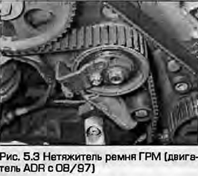
3. To remove the tensioner roller assembly on ADR (since 08/97) and AFY (since 08/97) engines, ensure that the springs are securely fastened with the drill shank (see paragraph 4) and unscrew the bolt from the eccentric hub. Unscrew the tensioner mounting bolts including the one on the hub and remove the spring assembly with the roller from the front engine strut (Fig. 5.3). Remove the bearing bushing.
4. To remove the semi-automatic tensioner on AHL engines, unscrew the mounting nut and remove the tensioner with the plate from the guide pin. Note that the tensioner base is fixed in the hole in the cylinder head.
Camshaft sprocket
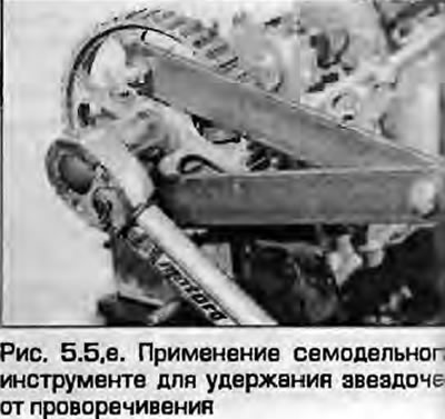
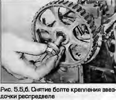
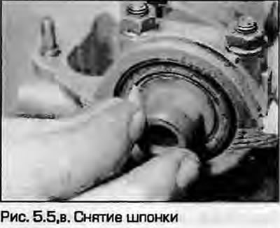
5. Loosen the camshaft sprocket mounting bolt, holding the sprocket against rotation with the tool shown in the figure. Remove the bolt together with the washer (if provided), an asterisk and (if provided) key (fig. 5.5, a-c).
Auxiliary shaft sprocket (except AHL engine)
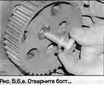
6. Loosen the sprocket mounting bolt, holding it from turning with a tool (see picture). Remove the bolt, sprocket and (if provided) key (fig. 5.6, a, b).
 |
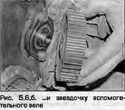 |
Note: the sprocket is installed with the TDC mark and the protrusion facing outward.
Crankshaft sprocket
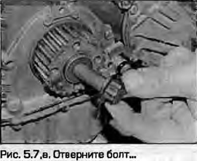
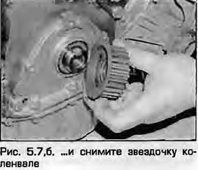
7. Loosen the crankshaft sprocket mounting bolt and remove the sprocket(fig. 5.7, a, b). The bolt is tightened very tightly, the crankshaft must be fixed from turning. On models with manual transmissions, engage the highest gear and ask an assistant to press the brake pedal firmly. If an automatic transmission is installed, remove the front cover of the gearbox and use a flat-head screwdriver to lock the toothed ring.
 |
 |
Examination
8. Clean the sprockets and make sure they are not worn or damaged. Rotate the tensioner roller and make sure it rotates smoothly.
9. Check the tensioner for wear or damage; replace the unit if necessary.
Installation
Crankshaft sprocket
10. Install the sprocket onto the crankshaft nose. While holding the crankshaft still in the same manner as when removing it, tighten the sprocket mounting bolt to the specified torque.
Note: Do not rotate the crankshaft, as this may bend the valves.
11. Install the timing belt as described in paragraph 4.
Auxiliary shaft sprocket (except AHL engines)
12. Install the key into the shaft groove and install the sprocket. Install the release bolt and tighten it to the specified torque, holding the sprocket from turning using the method used during removal.
13. Install the timing belt - see paragraph 4.
Camshaft sprocket
14. Install the key into the camshaft groove, put on the sprocket, tighten the bolt together with the washer (if any). Tighten the bolt to the specified torque, holding the sprocket from turning using the method used during removal. On ADR and AFY engines, the sprockets are installed with the protrusion facing outward.
15. Install the timing belt - see paragraph 4.
Tensioner/roller
16. Install the tensioner roller and spring assembly in the reverse order of removal.
17. Install the timing belt - see paragraph 4.