
Table of contents: General information ↓ Setting piston N4 to TDC ↓
General information
1. Camshaft, crankshaft and sprockets (except AHL engine) auxiliary shaft are driven by a toothed belt and rotate in phase. If the timing belt is removed during repairs, the shafts will be able to rotate independently and their rotation in phase will be disrupted.
2. The design of the engines discussed in this chapter is such that when the timing belt is removed, the pistons rest against the valves when the crankshaft rotates. Therefore, it is important to maintain the relative positions of the crankshaft, camshaft and (if provided) auxiliary shaft with the timing belt removed. This is achieved by setting the engine in a certain position (called TDC - top dead center) before removing the timing belt and preventing the shafts from turning. For the same purpose, when repairing the engine, the engine must be set to TDC, restoring the correct phasing of the shafts.
Note: On AHL engines, the coolant pump is also driven by the timing belt, but the pump phasing is not important. On ADP, APT, APW. AFY, AEB and AJL engines, the auxiliary shaft only drives the oil pump, so its phasing is also not important.
3. TDC - the highest point reached by the piston of the corresponding cylinder (in a four-stroke engine, twice per stroke; once on the compression stroke and once on the exhaust stroke). Usually (unless otherwise stated) this means the TDC of the first cylinder in the compression stroke. The cylinders are numbered from 1 to 4, starting from the timing belt.
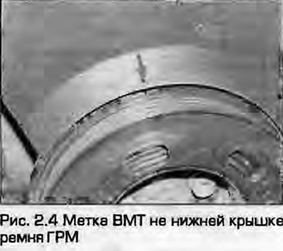
4. The crankshaft pulley has a mark which, when combined with the mark on the timing belt cover, indicates that piston No.1 (and, accordingly, piston No.4) is at TDC (Fig. 2.4).
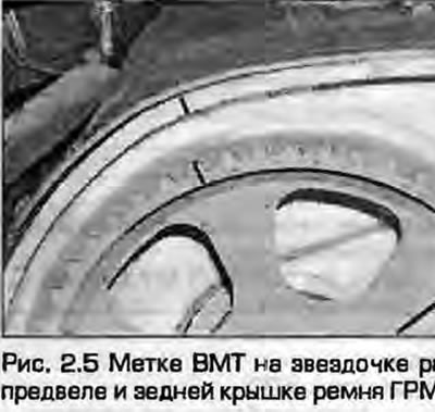
5. Camshaft sprocket (exhaust camshaft on DOHC engines) also has a TDC mark (Fig. 2.5). When it is aligned with the mark on the small upper timing belt cover or valve cover, the piston of cylinder No.1 is also set at TDC of the compression stroke.
6. In addition, the flywheel/faceplate also has marks that can be seen if the protective cover is removed from the clutch/gearbox bell. However, these marks are useless if the gearbox is removed - the corresponding mark is on the bell.
Setting piston N4 to TDC
7. Before starting work, turn off the ignition.
8. If necessary, remove the top engine cover.
9. On the ADP engine, remember the connection of the high-voltage wire of the first cylinder to the distributor cap, remove the cap and mark the position of the electrode of the first cylinder on the distributor body. This will help to determine the installation of the piston of the first cylinder at TDC by the runner.
10. Remove the spark plugs as described in Chapter 1A.
11. Using a wrench, turn the crankshaft clockwise on the crankshaft pulley bolt. To determine the compression, plug the spark plug hole of the first cylinder with a rubber plug (the pressure will push it out). On engines with a distributor, the runner will approach the mark applied in accordance with point 9.
12. Continue to rotate the crankshaft until the TDC mark on the crankshaft pulley or flywheel/faceplate aligns with the corresponding mark on the valve cover or bellhousing. For added assurance, remove the upper timing belt cover to view the marks on the camshaft sprocket.