
Table of contents: Removal ↓ Installation ↓
Note: Disassembly and repair of the cylinder head are described in chapter 2B.
Removal
1. Before starting work, disconnect the negative battery cable as described in chapter 5A.
2. Apply the handbrake, raise the front of the car with a jack and install safety supports.
3. Remove the top engine covers.
4. Remove the timing belt as described in paragraph 4. To do this, you will have to remove the front bumper and move the hood lock bracket away from the car.
5. Drain the coolant as described in chapter 1A.
6. Disconnect the exhaust pipe from the exhaust manifold - see chapter 4C.
7. Pull the intake pipe back and remove the gasket. On AEB and AJL engines (turbocharged) disconnect the crankcase ventilation hose that runs under the turbine, unscrew the two bolts securing the oil supply pipe to the cylinder head. Remove the heat shield, dismantle the turbine from the exhaust manifold.
7. Remove the air cleaner assembly together with the air flow sensor (MAF) as described in chapter 4A. Remove the air duct connecting the throttle body to the air filter.
Engines ADP, ADR, AFY, AEB and AJL
Note: On these engines, the cylinder head comes off with the exhaust manifold, but not the intake manifold.
8. Remove the intake manifold as described in chapter 4A.
9. If necessary, disconnect the wiring from the automatic camshaft adjuster.
AHL engines
Note: On this engine the cylinder head comes off with both intake and exhaust manifolds.
10. Loosen the clamps and disconnect the lower radiator hose from the radiator and engine, remove the expansion tank. Disconnect the upper hose from the cooling tube.
11. Loosen the connections and disconnect the fuel lines.
Note: Before removing the tubes, place rags around to collect any fuel escaping under pressure.
12. Disconnect the accelerator cable from the throttle body as described in chapter 4A, disconnect the vacuum hoses from the check valve and the brake booster.
13. Disconnect the wiring from the injectors, throttle position sensor (TPS) (not in the throttle body) and camshaft position sensor (on the left side of the engine). Disconnect the wiring from the intake air temperature sensor, which is located on the intake manifold. Disconnect the wiring from the oil temperature sensor on the right side of the cylinder head.
14. Remove the intake manifold support brackets from the manifold and the left side of the engine.
All engines
15. At the firewall behind the engine, disconnect the electrical connector for the oxygen sensor wiring and disconnect the wiring itself.
16. Disconnect the heater hose from the flange at the rear of the cylinder head, disconnect the wiring from the coolant temperature sensor screwed in there. On ACR, AFY, AEB and AJL engines, also disconnect the wiring from the second coolant temperature sensor at the rear of the cylinder head.
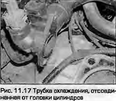
17. On AOR and AFY engines, disconnect the hoses from the upper coolant pipe mounted on the left side of the cylinder head. Remove the rear mounting bolts, then only loosen the front mounting bolt (tube bracket hole - with slot). Slide the tube back and remove it from the engine (fig. 11.17).
18. On ADP and AHL engines, disconnect the high-tension wires from the spark plugs and move the wires to the side.
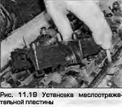
19. Remove the valve cover as described in paragraph 7. To do this, on all engines except ADP and AHL, you will have to remove the ignition coil and high-voltage wires. On ADR engines, remove the oil deflector plate (fig. 11.19).
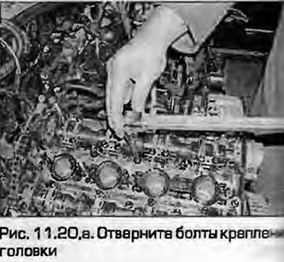
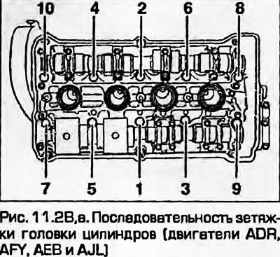
20. Using the Torx head, loosen the head mounting bolts one turn per pass in the reverse order of tightening (see fig. 11.28). Remove the bolts together with the washers (fig. 11.20, a, b).
 |
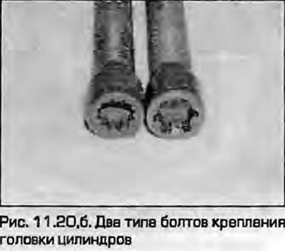 |
Note: The head bolts have been modified from Torx head bolts to Ribe head bolts - you may need two sockets to remove the old type bolts and install the new type bolts.
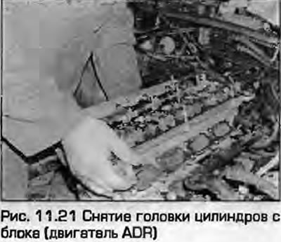
21. After removing all the bolts, remove the cylinder head from the block upwards together with the exhaust manifold (fig. 11.21). If the head is "dry", tap it with a wooden hammer. Do not pry the head with any levers.
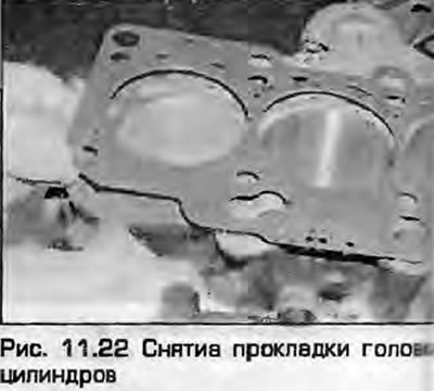
22. Remove the cylinder head gasket from the block (fig. 11.22).
23. If necessary, remove the exhaust manifold from the cylinder head as described in chapter 4B. On AHL engines, also remove the intake manifold as described in chapter 4A.
Installation
24. Thoroughly clean the mating surfaces of the cylinder head and block. Remove any oil or coolant that may have gotten into the threaded holes in the block for the head bolts. If this is not done, not only will the bolt tightening torque be incorrect, but the cylinder head will be completely free of oil and coolant; the hydraulic pressure when tightening the bolts may cause cracks in the block - the block will have to be thrown away. The head mounting bolts must be replaced with new ones without any conditions (please note the note in paragraph 19). Install the exhaust manifold with a new gasket onto the head as described in chapter 4B. On AHL engines, install the intake manifold as described in chapter 4A.
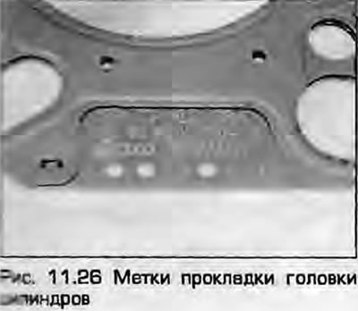
26. Place the new gasket on the block with the number and the OBEN TOP inscription facing up. Audi recommends that you remove the gasket from its packaging only before installation.
27. Carefully place the head on the block, aligning it with the guide bushings. Do not use any glues or lubricants. Insert new head mounting bolts with washers and tighten them by hand with a slotted head.
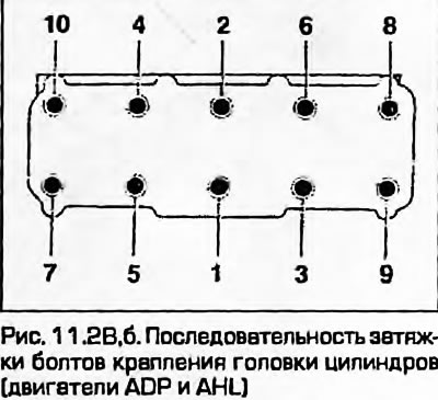
28. In the specified sequence (fig. 11.28, a, b) tighten the bolts in the first stage as indicated in Specifications.
 |
 |
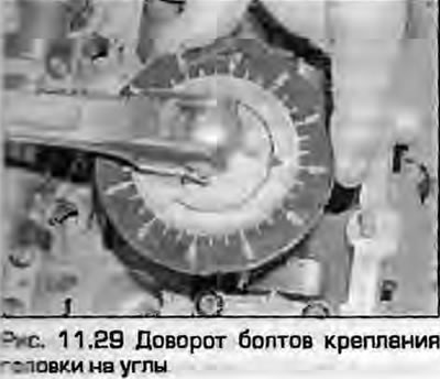
29. Tighten the bolts in the same sequence at the angles specified Specifications for stage 2 (fig. 11.29).
30. Install the valve cover as described in paragraph 7.
31. On ADP and AHL engines, connect the high-tension wires to the spark plugs.
32. On ADR and AFY engines, install the lower coolant pipe to the left side of the cylinder head, tighten the mounting bolts and connect the hoses.
33. Connect the heater hose to the flange at the rear of the cylinder head, connect the wiring to the temperature sensor on the flange. On ADR. AFY, AEB and AJL engines, connect the wiring to the second temperature sensor at the rear of the cylinder head.
34. Connect the wiring to the oxygen sensor and secure it in the connector.
AHL engines
35. Install the intake manifold support brackets and tighten their mounting bolts.
36. Connect the wiring to the injectors, TPS (on the throttle body) and the camshaft position sensor (front left on the engine). Connect the wiring to the intake air temperature sensor mounted in the intake manifold. Connect the wiring to the oil temperature sensor at the rear of the cylinder head.
37. Connect the accelerator cable to the throttle body as described in chapter 4A. Connect the vacuum hoses to the check valve and vacuum booster wires.
38. Connect the fuel lines and tighten their connections.
39. Install the expansion tank, connect the upper coolant hose to the tube, install the lower radiator hose and tighten the clamps.
Engines ADP, ADR. AFY, AEB and AJL
40. If necessary, connect the wiring to the camshaft position adjuster.
41. Install the intake manifold as described in chapter 4A.
All engines
42. Install the air filter together with the MAF sensor as described in chapter 4A, install the air intake duct connecting the air filter to the throttle body.
43. Connect the exhaust pipe with a new gasket as described in chapter 4B. On AEB and AJL engines (turbocharged) install the turbine on the intake manifold together with the heat shield. Secure the oil feed pipe with two bolts, connect the crankcase ventilation hose located above the turbine.
44. Install the timing belt as described in paragraph 4.
45. Fill with coolant as described in chapter 1A.
46. Install the upper engine covers
47. Lower the vehicle. Connect the battery as described in chapter 5A.