
Table of contents: Removal ↓ Installation ↓
Removal
1. Apply the handbrake and raise the front of the vehicle, install safety supports.
2. Remove the lower protective cover of the power unit.
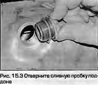
3. Place a basin under the pan, unscrew the drain plug and drain the engine oil. Clean the plug and, if necessary, replace the sealing ring. When the oil has drained, screw the plug back in and tighten it (Fig. 15.3). Remove the oil dipstick.
ADP engines
4. On models with air conditioning, mark the compressor drive belt to indicate the direction of rotation, remove the tensioner roller and remove the drive belt.
5. Loosen the bolts securing the front support to the engine (models with air conditioning) or to the subframe (models without air conditioning).
6. On models with air conditioning, remove the longitudinal support, then remove the jet support bracket from the engine.
7. Release the starter wiring from the engine stops by cutting the plastic clamp.
8. Unscrew the lower nuts of all engine mounts.
9. Unscrew the expansion tank mounting bolts on the left side of the engine compartment, disconnect the wiring from the lower coolant temperature alarm sensor, and move the tank to the side. Do not disconnect the hoses.
10. Remove the top engine cover, remove the crankcase ventilation hose and the air intake duct at the rear of the engine.
11. Release the oxygen sensor wiring from the mount on the engine shield.
12. Attach a hoist to the engine and lift it as high as possible without damaging any hoses or wiring. Make sure that the viscous coupling with the fan impeller does not rest against the radiator; if necessary, remove the fan as described in paragraph 5 of Chapter 3. Leave the fan inside the radiator diffuser.
13. Remove the intake manifold support bracket from the engine and gearbox.
14. Loosen the mounting bolts and remove the gearbox/engine bracket.
15. Unscrew the pan mounting bolts.
16. Remove the pan with the gasket. If the pan is "stuck", tap it lightly with a mallet, but do not pry it off with any levers.
Engines ADR, AFY, DEV and AJL
17. On models with air conditioning, mark the compressor drive belt to indicate its direction of rotation. Remove the tensioner pulley and remove the belt.
18. Remove the front mount from the engine (models with air conditioning) or from a subframe (models without air conditioning).
19. Not all models with air conditioning remove the longitudinal strut, remove the jet support bracket from the engine.
20. Release the starter wiring from the engine stops by cutting off the plastic ties.
21. On AEB and AJL engines, loosen the clamp and disconnect the turbocharger hose from the air tube on the lock bracket.
22. Unscrew the lower nuts of all engine mounts.
23. Remove the top engine covers.
24. Attach a hoist to the engine and lift it as much as possible without damaging the hoses and wiring. Make sure that the viscous coupling with the fan impeller does not rest against the radiator; if necessary, remove the fan as described in paragraph 5 of chapter 3. Leave the fan inside the radiator diffuser.
25. Support the left and right subframes with a trolley jack, placing a piece of board between the jack and the subframes. Mark the position of the subframes to maintain the wheel alignment angles after installation, unscrew the subframe mounting bolts. Unscrew the two front bolts first, then the rear ones. Lower the subframes together with the anti-roll bar to the floor.
26. On models with manual transmissions, back off the left mount nut approximately four turns so that it remains screwed on and flush with the bolt end.
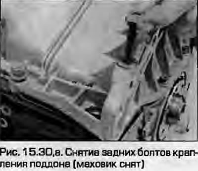
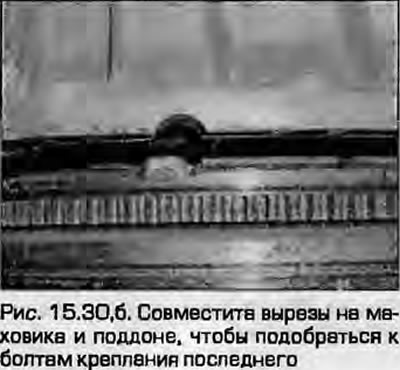
27. On models with automatic transmission, loosen the rear bolt on the left engine mount by a few turns, then unscrew the front bolt.
28. On models with any gearbox, loosen the rear bolt on the right engine mount a few turns, then remove the front bolt.
29. On DEV and AJL engines, unscrew the flange bolts and disconnect the turbocharger oil return pipe from the pan. Remove the gasket.
30. Remove the oil pan mounting bolts. On models with manual transmissions, the two rear bolts are accessible through cutouts in the flywheel - rotate the flywheel to set the cutouts in the desired position (fig. 15.30, a, b).
 |
 |
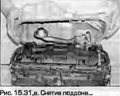
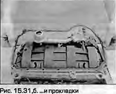
31. Remove the pan with the gasket. If the pan is stuck, tap it with a mallet (fig. 15.31, a, b).
 |
 |
AHL engines
32. Access to the front of the engine is possible if you remove the front panel with the hood lock bracket and move it away from the body as far forward as possible without disconnecting the hoses and wiring. To do this, remove the front bumper - see chapter 11. Unscrew the clips of the noise-insulating panel. Dismantle the air duct between the hood lock bracket and the air filter. To the left of the radiator, release the wiring from the fasteners. Unscrew the bolts securing the hood lock bracket assembly to the lower side members, unscrew the upper side bolts located behind the headlights. With an assistant, move the assembly as far forward as possible from the car. Audi mechanics use special brackets for fixing. They can be made by cutting threads on rods and screwing them into the side member.
33. On models with air conditioning, mark the direction of rotation of the compressor drive belt, remove the tensioner roller and remove the drive belt.
34. Remove the accessory drive belt as described in paragraph 6.
35. Remove the fan viscous coupling as described in paragraph 5 of chapter 3. The fan is removed by inserting a hex key from the rear, holding the coupling from turning with a bolt temporarily inserted from the rear, resting on the engine cylinder block.
36. Unscrew the support arm bracket from the front of the engine.
37. Release the starter wiring from the engine mount by cutting off the plastic ties.
38. Remove the support bracket between the intake manifold and the oil pan.
39. Remove the top nut from the left engine mount.
40. Having remembered the position of the engine mounts on both sides, unscrew the lower nuts of the mounts.
41. Connect a hoist to the engine and lift it until the air duct stops on the engine shield.
42. Remove the left engine mount completely.
43. Support the left and right subframes with a trolley jack, placing a piece of board between them. Mark the position of the subframes to maintain the wheel alignment angles after assembly. Unscrew the subframe mounting bolts. Unscrew the two front bolts, then the rear bolts. Lower the subframes together with the anti-roll bar to the floor.
44. Unscrew the left support mounting nut (about four turns), so that it remains flush with the end of the bolt.
45. Unscrew the pan mounting bolts, remove the pan. If the pan is "stuck", tap it with a mallet. The gasket is not installed, sealant is used to seal the joint.
Installation
46. Thoroughly clean the mating surfaces of the pan and block. On AHL engines, it is recommended to use a rotating wire brush to remove old sealant.
AHL engines
Warning: Do not try to apply a thicker layer of sealant in the hope of improving the seal - excess sealant may get into the pan and clog the oil pickup screen, causing oil starvation of the engine.
47. Apply a 2-3 mm wide bead of suitable silicone sealant to the mating surface of the oil pan. Spread the sealant evenly around the bolt hole, paying special attention to applying the sealant to the inner edge of the mating surface at the rear of the oil pan. After applying the sealant, attach the oil pan to the block immediately, first by tightening the mounting bolts, then tightening them "by hand". If the engine is removed from the car, make sure that the rear edge of the oil pan is flush with the rear wall of the cylinder block. Gradually and evenly tighten the oil pan mounting bolts to the prescribed torque. To monitor the curing moment of the sealant, refer to the instructions of its manufacturer. Usually it takes about 30 minutes from the moment the engine is filled with engine oil. If the engine is to be left without oil in the oil pan for a long time, remove the battery from the car and hang a warning sign so that no one gets the idea to start the engine.
All engines except AHL
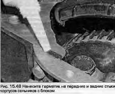
48. Apply a small amount of sealant to the mating surface of the block where the front and rear seal housings are installed (fig. 15.48).
49. Place a new gasket on the pan, place the pan on the block and tighten the bolts. Do not use sealants. Tighten the bolts to the specified torque in a diagonal sequence.
50. Install the block/gearbox bracket and tighten the bolts that secure it.
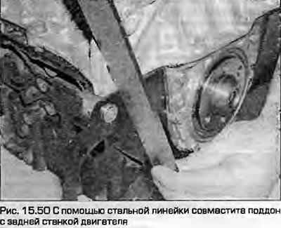
Note: If the oil pan is installed with the engine still in the vehicle and the transmission removed, ensure that the rear surface of the block/transmission bracket is flush with the adapter plate. If the adapter plate is removed, leave 0.8 mm (plate thickness) and install the bracket so that it protrudes 0.8 mm beyond the rear wall of the cylinder block (fig. 15.50).
All engines
51. The rest of the assembly procedure is the reverse of the removal procedure. Tighten the threaded connections to the prescribed torques. Fill the engine with the prescribed type and quantity of oil as shown in chapter 1A.
(The original version is on the portal: «AUDIMANUAL.RU»)