Repair Chevrolet Repair Toyota Repair Honda Repair AvtoVAZ Repair Mercedes-Benz Repair BMW Repair Opel
Home  |  Contacts  |  Sitemap  |    
English Русский
Български
Беларускі
Український
Српски
Hrvatski
Română
Polski
Slovenský
Magyar
AudiManual.ru


  • AUDI 80
  • AUDI 100
  • AUDI A3
  • AUDI A4
  • AUDI A6
  • AUDI A8
  • AUDI Q
  • OTHER
  • ARTICLES
B8 (2007-2015) B7 (2004-2008) B6 (2000-2006) B6 (2000-2006, petrol) B5 (1994-2001) B5 (1994-2001, petrol)

Accelerator cable — removal, installation and adjustment (Audi A4 B5)

  • Home
  • Audi A4
  • B5 (1994-2001)
  • Power unit
  • Fuel injection (gasoline)
  • Accelerator cable — removal, installation and adjustment
            0
Table of contents: Removal ↓ Installation ↓ Adjustment ↓
Application: Models with APT and APW engines do not have an accelerator cable, there is no mechanical connection between the throttle body and the accelerator pedal. An electric servomotor is mounted on the side of the throttle body, which controls the throttle valve. A pedal position sensor is installed in the accelerator drop unit.


Removal


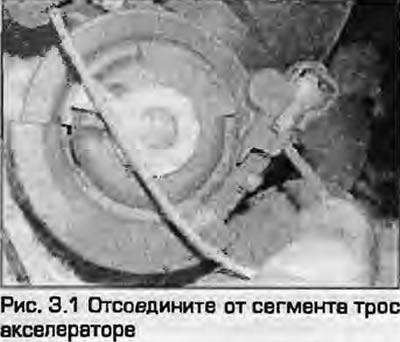
1. Disconnect the accelerator cable from the segment on the throttle body by turning the segment towards the throttle opening direction and removing the cable end (Fig. 3.1).

1. Disconnect the accelerator cable from the segment on the throttle body by turning the segment…


2. Note the position of the adjusting bracket on the worm of the outer sheath of the cable and pull the cable out of the rubber seal on the bracket (Fig. 3.2). Remove the seal from the bracket.

2. Note the position of the adjusting bracket on the worm of the outer sheath of the cable and pull…


3. Release the accelerator cable from all fasteners under the hood.


4. In the passenger compartment, remove the lower protective cover under the steering column.

5. Under the front panel, unhook the cable end from the accelerator pedal.

6. On models with automatic transmission, disconnect the kickdown switch wiring from the outer cable sheath under the hood.

7. Remove the cable fastening to the engine shield panel under the hood (Fig. 3.7).

7. Remove the cable fastening to the engine shield panel under the hood (Fig. 3.7).

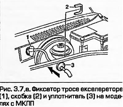
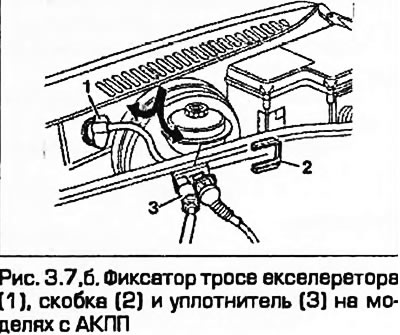
Note: On models with manual transmission, the mounting is located behind the engine shield panel.


8. On the firewall under the windshield, turn the cable mount counterclockwise a quarter turn (90°), aligning the triangular connection with the hole and remove the accelerator cable through the engine compartment.

Installation


9. Installation is the reverse procedure. Adjust the cable as described below. Correctly fasten the outer cable sheath to the engine shield.


Adjustment


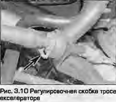
10. Adjust the position of the metal adjusting bracket on the outer casing of the cable at the throttle body so that when the accelerator pedal is fully depressed, the throttle valve opens to the stop (Fig. 3.10). When the pedal is fully released, the slack in the cable should be no more than 1 mm.

10. Adjust the position of the metal adjusting bracket on the outer casing of the cable at the…


11. On models with automatic transmission, check the kick-down switch/sensor - before the end of the cable travel, when you press the accelerator pedal, you should hear a click. You can check the operation of the switch with an ohmmeter. To do this, carefully disconnect the switch wiring connector in the rear of the engine compartment and connect an ohmmeter to the two terminals. When you release the accelerator pedal, the ohmmeter should show infinity, which means that the switch contacts are open. Ask an assistant to smoothly press the accelerator pedal. Before the pedal has reached its full travel, the ohmmeter should show zero, which means that the switch contacts are closed.
The article was checked by auto expert Timur Bazhenov
This article is available at russian, bulgarian, belarusian, ukrainian, serbian, croatian, romanian, polish, slovak, hungarian

Share information:
Previous articles
Audi A4 B5: Fuel injection (gasoline)
Next articles

Air Cleaners and Air Intake Ducts — Removal and Installation
General information and precautions
Multi-Point Fuel Injection Specifications for Gasoline Engines
Bosch Motronic Fuel Injection Control System Components
Simos injection control system components
Fuel filter — replacement
Fuel pump and fuel level indicator sensor unit


Similar articles on other Audi car models:
Accelerator cable — removal, installation and adjustment Audi 80 B3 (1986-1991, petrol)
Hood Lock Cable — Removal, Installation and Adjustment Audi 100 C3 (1982-1990, diesel)
Removal and installation the parking brake lever and cable Audi A3 Type 8L (1996-2003)
Removal and installation the timing belt — Diesel engine… Audi A6 C5 (1997-2004)
Removal and installation the engine Audi A8 D2 (1994-2002)
Turbocharger — removal and installation Audi Q5 Type 8R (2008-2017)
Removal, installation and adjustment of the hood Audi A2 (1999-2005)
Link to this page in different formats


Visitor comments

No comments yet


How much will 46 + 23 =


A4(B8, 2007-2015) 
  • General information
  • Operating instructions
  • Power unit
  • Petrol engines 1.8 l
  • Petrol engines 1.8/2.0 l
  • Petrol engines 3.0 l
  • Petrol engines 3.2 l
  • Fuel system (petrol)
  • Diesel engines 2.0 l (CA*)
  • Diesel engines 2.0 l (CJCB)
  • Diesel engines 2.7/3.0 l
  • Diesel engines 3.0 l
  • Fuel system (diesel)
  • Transmission
  • Manual gearbox 0B1
  • Manual gearbox 0B2
  • Manual gearbox 0B3
  • Manual gearbox 0B4
  • Automatic transmission 0B5
  • Automatic transmission 0B6
  • Automatic transmission 0AW
  • All-wheel drive system
  • Chassis
  • Front suspension
  • Rear suspension
  • Brake system
  • Steering system
  • Body
  • Exterior
  • Interior
  • Seats
  • Doors, locks and windows
  • Security system
  • Heating and air conditioning
  • Electrical equipment
  • Audio system
  • Power devices
  • Equipment and devices
  • Lighting and lamps
  • Electrical circuits
 
A4(B7, 2004-2008) 
  • General information
  • Introduction to manual
  • Troubleshooting
  • Operating instructions
  • Maintenance
  • Power unit
  • Petrol engines 2.0 (ALT)
  • Petrol engines 2.0 (TFSI)
  • Petrol engines 1.8 (MPI)
  • Diesel engines
  • Cooling system
  • Air conditioner
  • Fuel and exhaust system
  • Ignition system
  • Starting and charging
  • Transmission
  • Clutch
  • Manual gearbox
  • Automatic gearbox
  • Drive shafts
  • Chassis
  • Brake system
  • Front suspension
  • Rear suspension
  • Steering
  • Body
  • Exterior
  • Interior
  • Electrical equipment
  • Equipment and devices
  • Lighting and signaling
  • Windscreen wipers and washers
  • Electrical diagrams
  • Electrical diagrams (since 2007)
 
A4(B6, 2000-2006) 
  • General information
  • Vehicle Description
  • User manual
  • Maintenance
  • Power unit
  • Gasoline engine
  • Diesel engine
  • Lubrication system
  • Cooling system
  • Supply system
  • Injection system
  • Exhaust system
  • Ignition and control
  • Transmission
  • Gear box
  • Clutch and drive shafts
  • Chassis
  • Brake system
  • Car suspension
  • Steering
  • Body
  • Heating and ventilation
  • Exterior (external elements)
  • Interior (internal elements)
  • Electrical equipment
  • Power devices
  • Lighting and appliances
  • Electrical circuits
 
A4(B6, 2000-2006, petrol) 
  • General information
  • Introduction to the guide
  • Car care
  • Power unit
  • Engine repair
  • Lubrication system
  • Cooling system
  • Injection and control system
  • Ignition system
  • Power and exhaust system
  • Transmission
  • Clutch and drive shafts
  • Car gearbox
  • Chassis
  • Suspension and wheels
  • Steering
  • Brake system
  • Body
  • Interior
  • Exterior
  • Electrical equipment
  • Equipment and devices
  • Lighting and signaling
  • Power devices
  • Electrical circuits
 
A4(B5, 1994-2001) 
  • General information
  • Introduction to the guide
  • Car care
  • Maintenance (gasoline)
  • Maintenance (diesel)
  • Power unit
  • Gasoline engines
  • Diesel engines
  • Engine overhaul
  • Cooling system
  • Fuel injection (gasoline)
  • Fuel system (diesel)
  • Exhaust system
  • Ignition system
  • Transmission
  • Clutch
  • Mechanical gearbox
  • Automatic gearbox
  • Drive shafts
  • Chassis
  • Brake system
  • Car suspension
  • Steering
  • Body
  • Exterior
  • Interior
  • Doors, locks and windows
  • Heating and ventilation
  • Electrical equipment
  • Power devices
  • Equipment and devices
  • Electrical circuits
 
A4(B5, 1994-2001, petrol) 
  • General information
  • Vehicle description
  • Maintenance
  • Power unit
  • Engine repair
  • Turbocharging
  • Exhaust system
  • Cooling system
  • Ignition system
  • Fuel system
  • Motronic injection system
  • MPI and MPFI injection system
  • Transmission
  • Clutch
  • Gearbox and shafts
  • Chassis
  • Steering
  • Car suspension
  • Brake system
  • Wheels and tires
  • Body
  • Heating and ventilation
  • Body parts
  • Electrical equipment
  • Fuses and relays
  • Power devices
  • Lighting and lamps
  • Tools and devices
  • Electrical circuits
 
AudiManual.ru © 2017-2026 · Mobile version · Feedback · Sitemap: EN BG BY UA RS HR RO PL SK HU · Site search · News and articles
80 B2 · 80 B3 petrol · 80 B3 · 80 B4 · 100 C3 diesel · 100 C3 petrol · 100 C3 · 100 C4 petrol · 100 C4 · A3 Type 8L · A4 B5 petrol · A4 B5 · A4 B6 petrol · A4 B6 · A4 B7 · A4 B8 · A6 C4 · A6 C5 · A6 C5 Allroad · A8 D2 · Q5 Type 8R · Q7 Typ 4L · Audi A2 ·
This site uses cookies 🍪. Click the button to accept this fact.