
Table of contents: Engine 1.8-I/125 hp. ↓ Engine 1.8-I/150 hp. ↓
Engine 1.8-I/125 hp.
The water pump is located in the cylinder block and is driven by a toothed belt.
Removal
Drain the coolant
Remove the poly V-belt.
Unscrew the three bolts securing the poly V-belt tensioner mechanism and remove it.
Set the piston of the first cylinder to the top dead center in the compression stroke, loosen the tension of the toothed belt and remove it from the camshaft pulley and water pump. The vibration damper and the lower toothed belt cover can be left in place.
Caution: To protect the timing belt from coolant, cover the timing belt with a rag or plastic.
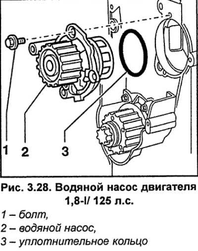
Unscrew bolts 1 and remove water pump 2 with sealing ring 3 (Fig. 3.28).
While turning the water pump shaft, check the condition of the water pump bearings and replace them if necessary.
Installation
Clean the sealing ring installation area.
Soak the new O-ring in coolant.
Install the pump so that the drain hole on the pump body is located at the bottom.
Screw the pump with bolts, tightening them to a torque of 15 Nm.
Install the timing belt.
Install and secure the poly V-belt tensioner with bolts, tightening them to a torque of 25 Nm.
Install the poly V-belt.
Fill the cooling system with coolant and bleed air from the system.
Engine 1.8-I/150 hp.
The water pump is mounted on the cylinder block together with a bracket with an alternator, power steering pump and radiator fan.
Removal
Remove the thermostat.
Caution: The air conditioning compressor drive poly V-belt must not be removed.
Remove the poly V-belt from the generator drive and the radiator fan viscous coupling.
Remove the water pump drive V-belt.
Remove the generator.
Unscrew the three bolts securing the poly V-belt tensioner mechanism and remove it.
Unscrew the intake pipe support bracket from the cylinder block.
Unscrew the poly V-belt pulley from the power steering pump.
Unscrew the power steering pump and, without disconnecting the hoses from it, move it to the side and secure it to the engine with soft wire.
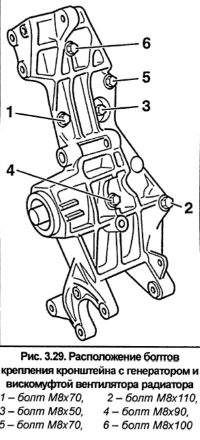
The bracket with the water pump, generator and viscous coupling of the radiator fan is secured with bolts of different lengths, so mark the bolts before unscrewing them (see fig. 3.29). Unscrew the bolts and remove the bracket. Tighten the bracket mounting bolts in sequence 1-6 (Fig. 3.29).
Loosen the clamps and remove the coolant hoses from the water pump.
Remove the bolts and remove the water pump from the bracket.
Installation
While turning the water pump shaft, check the condition of the water pump bearings and replace them if necessary.
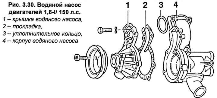
Attention. If the paper gasket 2 (Fig. 3.30) or the bearing housing 1 with the impeller was replaced, screw the pump cover on with bolts, tightening them to a torque of 10 Nm.
Install the water pump with a new sealing ring and bracket on the engine block and, in accordance with the previously applied markings, screw on the bolts, tightening them to a torque of 25 Nm. Tighten the bolts in sequence 1-6 (Fig. 3.29).
Bolt the front timing belt cover to the water pump housing.
Install the thermostat.
Connect the cooling system hoses to the water pump and secure them with clamps.
Install the bracket for the suction pipe and secure it with bolts, tightening them to a torque of 25 Nm.
Install and secure the poly V-belt tensioner with bolts, tightening them to a torque of 25 Nm.
Install the generator.
Install the V-belt and poly V-belt.
Fill the cooling system with coolant and bleed air from the system.
After a test drive, check the cooling system hoses and water pump for leaks.