
Table of contents: Draining the coolant ↓ Filling the cooling system ↓
The coolant must be replaced after any work on the cooling system components with draining the coolant. If the cylinder head, cylinder head gasket, radiator or oil heat exchanger was replaced during repairs, only fresh coolant must be added. This is due to the fact that the anti-corrosion additive precipitates during operation of the coolant and creates anti-corrosion protection. In previously used coolant, the anti-corrosion additives are less active in order to form a protective layer on newly installed parts.
Draining the coolant
Open the hood and remove the cap from the expansion tank.
Safety instructions. When opening the expansion tank cap on a hot engine, be careful, as escaping steam can cause severe burns. To do this, cover the expansion tank cap with a thick layer of cloth and slowly unscrew the cap until a hissing sound is heard. After the hissing stops, slowly unscrew and remove the cap from the expansion tank. Remove the cap from the expansion tank only at temperatures below +90°C.
Raise the front of the vehicle and support it on stands. Remove the lower engine compartment splash shield.
Place a clean container under the radiator to collect any leaking coolant.
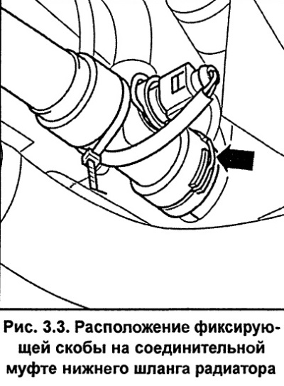
Petrol engines.Disconnect the lower hose from the radiator. To do this, remove the retaining clip (see fig. 3.3) on the side of the coupling, then disconnect the hose. Collect the coolant in a prepared container.
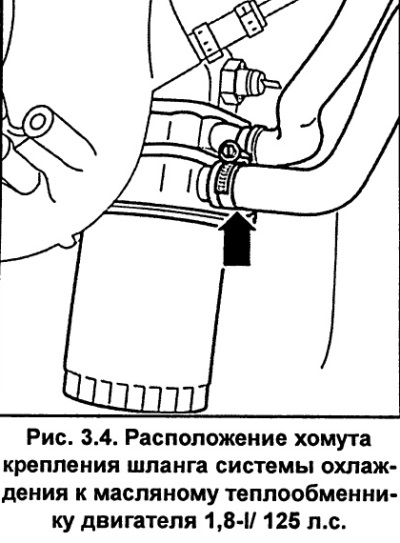
Engine 1.8-I/ 125 hp. Additionally, disconnect the cooling system hose from the oil heat exchanger by loosening the clamp and removing the hose from the heat exchanger (see fig. 3.4). The oil heat exchanger is located at the base of the oil filter. Collect the coolant in a prepared container.
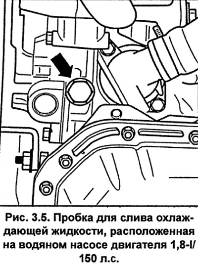
Engine 1.8-I/150 hp. Remove the coolant drain plug located on the water pump and drain the coolant from the engine block (see fig. 3.5). Collect the coolant in a prepared container.
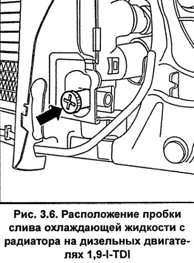
Engine 1.9-I-TDI. Using a coin or wide-blade screwdriver, remove the radiator coolant drain plug (see fig. 3.6). Collect the coolant in a prepared container.
To drain the coolant more completely, remove the thermostat.
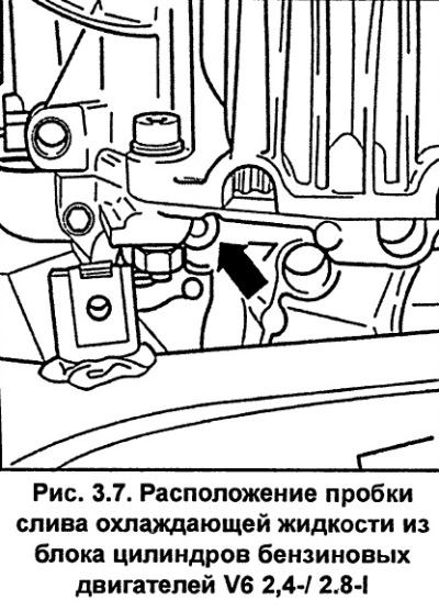
Petrol engines V6 2.4-/2.8-I.Using a hex socket wrench, unscrew the drain plug on the engine block (see fig. 3.7). The plug is located at the bottom on the left side, near the gearbox flange.
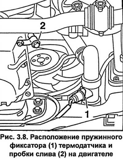
Engine V6- 2.5-I-TDI.Remove the spring clip 1 securing the temperature sensor to the cooling system hose in the lower right part of the engine. Remove the temperature sensor. Drain the coolant from the engine by unscrewing the drain plug 2 (Fig. 3.8).
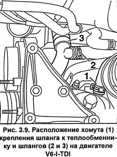
On the left side of the engine, disconnect the cooling system hose from the oil heat exchanger. To do this, use special pliers, for example, HA2ET 798-5, loosen clamp 1 and remove the hose (Fig. 3.9). Do not remove hoses 2 and 3 (Fig. 3.9).
Filling the cooling system
If the coolant is heavily contaminated, flush the cooling system. Since it is impossible to drain the coolant completely from the cooling system, it is recommended to flush the cooling system each time the coolant is drained.
Prepare the required amount of coolant from 50% water and 50% antifreeze with anti-corrosion additive "G12 AD8".
Petrol engine.Connect the lower coolant hose to the radiator and secure the connector with the retaining clip.
Engine 1.9-I-TDI.Screw the coolant drain plug into the radiator and tighten it to 10 Nm. Install the thermostat.
Engines 1.8-I/125 hp and V6- 2.5-I-TDI.Connect the cooling system hose to the oil cooler and secure it with a clamp.
Engine V6-2.5-I-TDI.Install the temperature sensor on the cooling system hose at the lower right side of the engine and secure it with spring clip 1 (Fig. 3.8). Screw drain plug 2 into the engine cylinder block.
Engine 1.8-I/150 hp. Screw the coolant drain plug into the water pump and tighten it to 30 Nm.
Petrol engines V6 2.4-/2.8-I.Screw the threaded plug with a new sealing ring into the engine block and tighten it to a torque of 20 Nm.
Install the lower engine splash shield and lower the vehicle to the ground.
Move the heating system temperature control to the maximum temperature position.
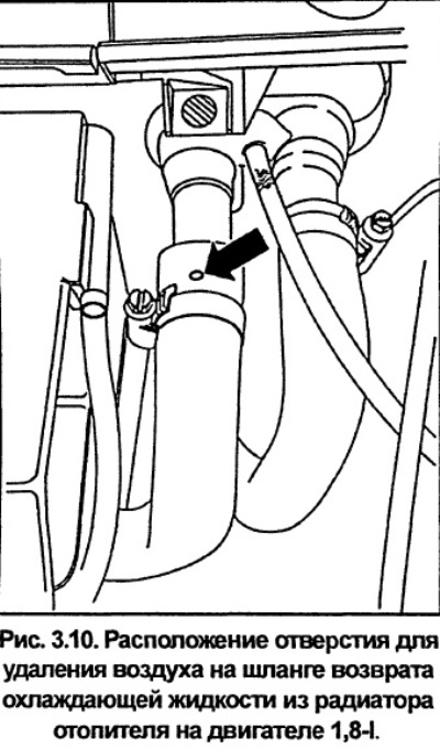
Engine 1.8-I.Near the engine compartment bulkhead, loosen the clamp securing the coolant return hose from the heater radiator and move the hose off the fitting so that the fitting does not block the hole in the air bleed hose (see fig. 3.10).
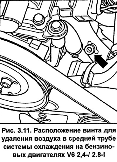
Petrol engines V6 2.4-/2.8-I. The air bleed screw is located on the front side in the middle pipe of the cooling system, in the area between the servo pump and the left cylinder head (see fig. 3.11).
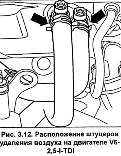
Engine V6-2.5-I-TDI.On the front side of the engine compartment bulkhead, unscrew the air bleed nipples located at the connection point of the heater radiator hoses by two turns (see fig. 3.12).
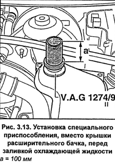
Instead of the expansion tank cap, screw in the VAG 1274/9 threaded adapter with a tube with a diameter of 42 mm and a height of 100 mm (see fig. 3.13). This is necessary to completely fill the engine cooling system with coolant and remove air from it. If you do not have a special device, you can make one yourself. You can also unscrew the expansion tank from the bracket and lift it with the connected hoses by 10 cm and fix it in this position.
Engines 1.8-I.Fill the cooling system with coolant until the coolant starts to flow out of the hole in the heater coolant return hose. Push the hose onto the fitting until it stops and secure it with a clamp.
Petrol engines V6 2.4-/2.8-I. Fill the expansion tank with coolant until coolant flows out through the air bleed screw in the middle pipe of the cooling system. Tighten the screw to 20 Nm.
Engine V6-2.5-I-TDI. Fill the expansion tank with coolant until the coolant flows out through the air bleed nipples located where the heater radiator hoses are connected. To improve air bleed, squeeze the thicker hose several times with your hand. Screw in the bleed nipples.
If the expansion tank was removed from the bracket, install it on the bracket. Remove the device that was installed in place of the cap from the expansion tank and screw the cap onto the expansion tank.
Start the engine and let it run for 3 minutes at 2000 rpm.
Let the engine idle until the lower radiator hose is warm, then turn off the engine.
Check the coolant level and top it up if necessary.
When the engine is hot, the coolant level should be at the MAX mark, and when the engine is cold, it should be between the MAX and MIN marks.