
Table of contents: Engine 1.8-I/125 hp. ↓ Engines 1.8-I/150 hp and 1.9-I/110… ↓ Engines V6 2.4-/2.8-I (165/193 hp) ↓ Engine V6 2.5-I-TDI/150 hp. ↓ Checking the Thermostat ↓
Engine 1.8-I/125 hp.
Removal
The thermostat is located in the exhaust pipe of the cylinder block behind the generator.
Remove the ground cable from the battery.
Attention
- When disconnecting the wires from the battery terminals, the memory units of the control units erase the data on the recorded faults, so before disconnecting the wires, you must contact a workshop to recall the faults recorded in the memory. After connecting the wires to the battery terminals, it is necessary to activate and reprogram the electric windows, as well as the position of the rear-view mirrors and seats.
- If the car has a radio receiver with a code, then before disconnecting the wires from the terminals from the battery, check that there is a code to reactivate the receiver. Otherwise, the radio receiver can only be put into operation at a specialized station.
Drain the coolant from the cooling system.
Remove the power steering fluid reservoir housing from the spring clips.
Remove the electrical connectors of the anti-lock braking system (ABS)from the holder (see fig. 3.14). Do not disconnect electrical connectors.
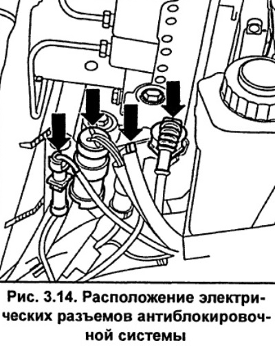
Lift up the electrical connector holder.
Unscrew and remove the air duct connecting the front crossmember and the air filter.
Remove the generator.
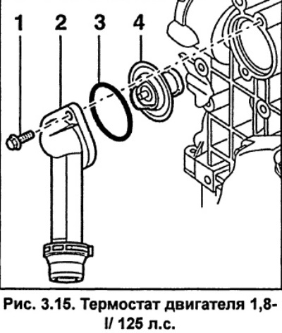
Unscrew the two bolts and remove the connecting pipe from the engine cylinder block (see fig. 3.15). Remove the thermostat together with the sealing ring. A new sealing ring must be used when installing.
Check the thermostat and replace it if necessary.
Installation
Clean the area where the sealing ring will be installed.
Lubricate the new O-ring with coolant and install it on the thermostat.
Install the thermostat into the cylinder head so that the air bleed valve is located at the top.
Install the cooling system connecting pipe and screw in the bolts, tightening them to a torque of 15 Nm.
Install the generator.
Install the air duct connecting the front crossmember and the air filter.
Connect the ground wire to the battery. Repeat the steps to memorize the position of the seats, mirrors, etc., and also set the time on the clock and enter the code into the radio.
Secure the ABS electrical connectors to the holder.
Secure the power steering fluid reservoir housing to the spring clips.
Fill the cooling system with coolant.
Start the engine and check the cooling system for leaks.
Engines 1.8-I/150 hp and 1.9-I/110 hp.
The thermostat is located in the water pump housing.
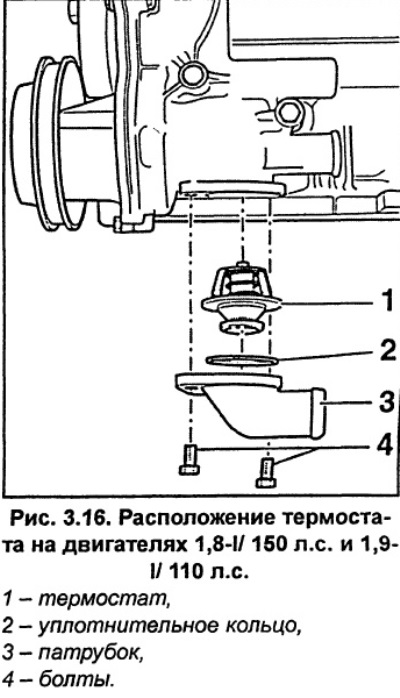
Drain the coolant Remove the two bolts securing the coolant hose to the bottom of the water pump and drain the coolant into a suitable container. Move the coolant hose with the hose attached to it to the side (see fig. 3.16).
Remove the thermostat and O-ring. A new O-ring must be used when installing the thermostat.
Check the thermostat and replace it if necessary.
Installation
Install the thermostat with a new o-ring.
Install the pipe and secure it with bolts, tightening them to a torque of 10 Nm.
Fill the cooling system with coolant.
Start the engine and check the cooling system for leaks.
Engines V6 2.4-/2.8-I (165/193 hp)
The thermostat is located in the cooling system hose in front of the engine cylinder block.
Drain the coolant Remove the poly V-belt Loosen the toothed belt tension and remove it from the camshaft pulleys.
Caution: To protect the timing belt from coolant, cover the timing belt with polyethylene.
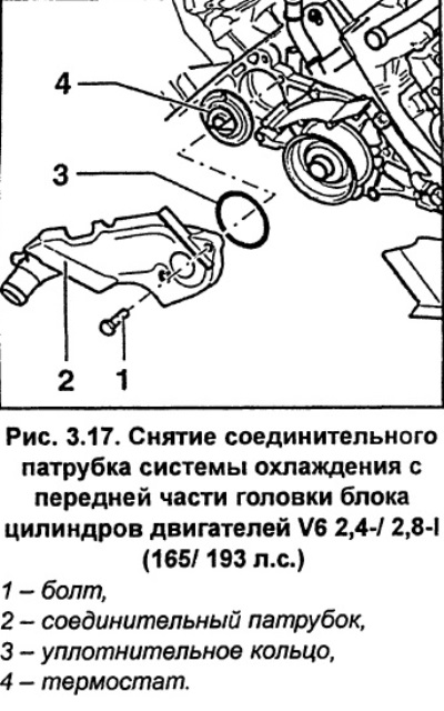
Remove the two bolts and the coolant system connecting pipe from the front of the cylinder block (see fig. 3.17).
Remove the sealing ring and thermostat from the cylinder block. Check the thermostat and replace it if necessary.
Installation
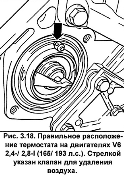
Install the thermostat in the cylinder block so that the air bleed valve is located on top (see fig. 3.18).
Install the cooling system connecting pipe with a new sealing ring and screw on the bolts, tightening them to a torque of 10 Nm.
Install the timing belt onto the camshaft pulleys.
Install the poly V-belt.
Fill the cooling system with coolant.
Start the engine and check the cooling system for leaks.
Engine V6 2.5-I-TDI/150 hp.
Removal
The thermostat is located in the cooling system hose in front of the engine cylinder block.
Drain the coolant
Remove the poly V-belt.
Remove the viscous coupling radiator fan pulley bolt.
Unscrew the bolts securing the radiator fan bracket with viscous coupling and idler pulleys 1 and 2 (Fig. 3.19).
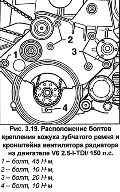
Unscrew the lower timing belt cover mounting bolt 4 (Fig. 3.19).
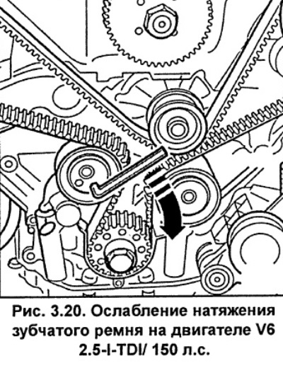
Using an 8mm socket wrench, turn the timing belt tension roller clockwise and secure it in the retracted position with a 2mm pin (see fig. 3.20).
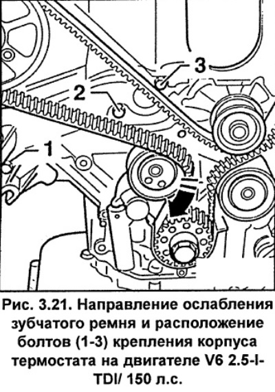
Pull the timing belt on the tension roller in the direction of the arrow shown in Figure 3.21.
Caution: Do not remove the timing belt from the tension roller, otherwise the belt may come off the other pulleys and you will have to perform installation operations.
Unscrew bolts 1-3 and remove the thermostat housing (Fig. 3.21).
Remove the thermostat with the sealing ring.
Check the thermostat and replace it if necessary.
Installation
Install the thermostat in the cylinder block so that the air bleed valve is located on top (see fig. 3.18).
Install a new O-ring.
Install the thermostat housing and secure it with bolts. Apply a locking compound, such as Loctite 243, to the threads of bolt 2 (Fig. 3.21). Screw in and tighten bolts 1-3 to a torque of 10 N·m.
Move the timing belt back over the tension roller and remove the pin.
Adjust the timing belt tension.
Install and bolt the radiator fan bracket with viscous clutch and idler pulleys and the lower timing belt cover (see fig. 3.19).
Install the poly V-belt and the viscous coupling radiator fan.
Checking the Thermostat
Remove the thermostat.
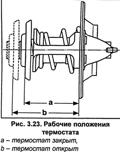
Measure the length of the closed thermostat a (Fig. 3.23).
A rough test of the thermostat's functionality can be done by hanging it on a thread in a glass vessel filled with water and heating the water to boiling point, while the thermostat should not touch the walls of the vessel (see fig. 3.22).
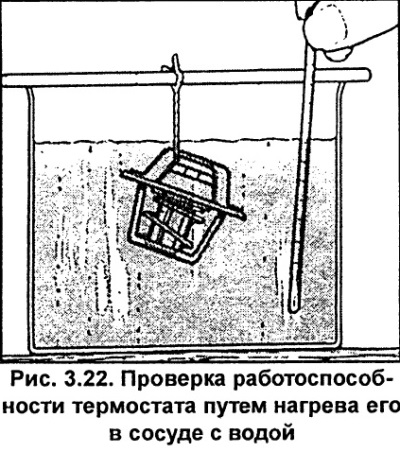
Monitor the water temperature with a thermometer. The thermostat should start to open at 87°C and open completely at 102°C. Otherwise, replace it.
The thermostat opening temperature is indicated on the thermostat housing.
When heating the thermostat to a temperature of 102°C, the length of the open thermostat b should be greater than the length of the closed thermostat a by 8 mm (see fig. 3.23).
A thermostat that does not close when the water cools also needs to be replaced.
Install the thermostat.
(This article was previously published on the resource: audimanual.ru)