
Table of contents: Electric fan switch sensor ↓ Temperature gauge/alarm temperature… ↓ Temperature sensor of the engine… ↓
Electric fan switch sensor
Examination
1. Welding of sensors is described in paragraph 5, as part of the procedure for welding an electric fan.
Removal
Note: The engine and radiator must cool completely before removing the sensor.
2. The sensor is mounted on the left side of the radiator. Above the lower hose fitting, on most models it is accessible from above. If it is leaking completely, apply the handbrake, raise the front of the car and install safety supports. Loosen the mounting screws and remove the lower engine cover so that the sensor is accessible from below.
3. Disconnect the ground wire from the battery.
4. Drain the coolant to the sensor level as described in the relevant section chapters 1. If doing otherwise, prepare a suitable plug to install it immediately after unscrewing the sensor. In any case, try not to damage the radiator and do not allow foreign particles to enter it.
5. Disconnect the multi-pin connector from the fan switch.
6. Carefully unscrew the sensor from the radiator and remove the sealing ring from it (if provided). Plug the hole to prevent fluid loss.
Installation
7. If the previous sensor was installed with a sealing ring, install a new one. If there was no sealing ring, apply sealant to the threaded part of the sensor.
8. Installation - reverse procedure. Tighten the sensor to the specified torque and fill the system with coolant as described in the relevant section chapters 1.
9. Finally, start the engine and warm it up to operating temperature. Check that the fan turns on in a timely manner.
Temperature gauge/alarm temperature indicator sensor
Examination
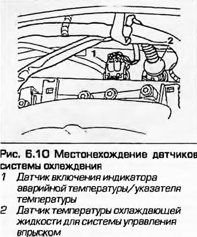
10. Not all models have a sensor installed in the outlet of the cooling system in the left rear part of the cylinder head (Fig. 6.10). If two sensors are installed, the outer one of the two is the temperature gauge sensor (internal sensor - for engine control unit).
11. The temperature gauge receives stabilized power from the instrument panel (from the ignition switch through the fuse). The device is connected to the "ground" via a sensor. The sensor contains a thermistor - an electronic element whose electrical resistance decreases according to a certain schedule with increasing temperature. If the temperature is low, the sensor resistance is high, the current through the pointer decreases, the device arrow deviates into the blue (cold) sector of the scale. As the temperature increases, the reverse process occurs, the arrow creeps into the red sector. A faulty sensor must be replaced.
12. The emergency temperature indicator is powered in the instrument panel. The negative terminal is connected to the "ground" via a sensor, which is essentially a bimetallic pair of contacts that close when the engine reaches the emergency temperature.
13. The sensors are mounted in one housing with a four-pin connector.
14. If a malfunction has occurred in the instrument cluster, first check the supply voltage to all the instruments on the panel. If there is no voltage or it is incorrect, the voltage stabilizer may be faulty, which in this case must be replaced (the stabilizer is part of the printed circuit board of the instrument cluster - see chapter 12). If the fault is only in the temperature gauge, perform the following check.
15. If the instrument needle constantly shows low temperature, although the engine is warm, disconnect the wiring connector from the sensor and connect it to the "ground" - a metal part of the engine. With the ignition on, the needle should move to the high temperature area on the instrument. If this is not the case, the faulty sensor must be replaced. If the needle does not move even when the connector is shorted to ground, remove the instrument panel as described in chapter 12 and check the condition of the circuit between the sensor connector and the device and the power supply to the device. If the circuit is in good condition and the voltage is supplied, the device is faulty and it needs to be removed.
16. If the instrument pointer indicates a high temperature when the engine is cold, disconnect the connector from the sensor. If the pointer returns to the low temperature range with the ignition on, the sensor is faulty. If the pointer still does not move, check the condition of the circuit as described above.
17. This basic principle also underlies the check of the emergency temperature indicator. The indicator should light up if the connector of its sensor is shorted to ground.
Removal
1S. Drain the coolant as described in chapter 1A or 1B. If doing otherwise, unscrew the expansion tank cap to relieve system pressure and have a new sensor assembly or suitable plug handy. If you use a plug, be careful not to damage the sensor hole or allow foreign particles to enter the system.
19. On diesel engines, remove the plugs, unscrew the mounting nuts and remove the top engine cover to access the sensor.
20. Disconnect the multi-pin connector and determine whether the sensor is screwed in or inserted.
21. If the sensor is screwed in, unscrew it from the engine and remove the sealing washer.
22 If the sensor is inserted, press it down and release the retainer. Remove the sensor and its sealing ring from the engine.
Installation
23. If the sensor is screwed in, install a new O-ring, secure the sensor and tighten it securely.
24. If the sensor is insertable, replace the sealing ring and insert the sensor, securing it with the retainer.
25. Connect the wire connector and fill the system as described in the relevant section chapters 1 or top up as described in Weekly checks, on diesel engines, install the top engine cover.
Temperature sensor of the engine control unit
26. On all models, the sensor is installed in the outlet of the cooling system in the left rear part of the cylinder head. If two sensors are installed, the outer of the two temperature gauge sensors (internal sensor - for engine control unit).
27. The sensor is a thermistor (see item 11). The engine control unit supplies the sensor with voltage by measuring the current passing through the sensor, calculating the engine temperature. Together with data from other sensors, the information received is processed and used to control the injection ignition timing, idle speed, glow plugs of diesel engines, etc.
28. If the sensor circuit is damaged, the ECU will switch to the backup mode, the engine will continue to run, although with reduced efficiency. At the same time, a warning indicator will light on the instrument panel - contact your Audi/VAG dealer for advice. The sensor itself can only be checked using specialized equipment at the dealer's service center. DO NOT attempt to check the sensor using other equipment, as this may damage the ECU.
Removal and installation
29. Refer to the information provided in paragraphs 18...25.
(The original article is available on the online resource: «audimanual.ru»)