
Table of contents: Removal ↓ Inspection ↓
Removal
1. The primary function of the timing belt is to drive the camshaft, but it is also used to drive the water pump. The fuel pump is driven from the rear end of the camshaft by an additional drive belt. If the belt breaks or slips, the valve timing will be disrupted. This can cause the valves to hit the pistons, causing serious damage.
2. For this reason, it is important to regularly inspect the timing belt for signs of wear and contamination and check its tension.
3. Removal of the inner timing belt cover is described as part of the cylinder head removal procedure (see Chapter 11).
4. Before starting work, disconnect the negative cable from the battery.
5. Apply the handbrake, then jack up the front of the car and support it on axle stands. Remove the lower engine compartment shield and remove it from under the car.
6. Remove the front bumper as described in Section 11.
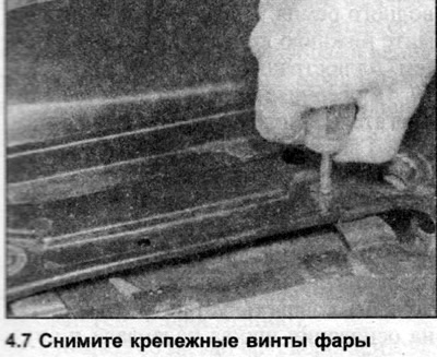
7. Remove both front headlights as described in Section 12 (see illustration).
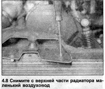
8. Disconnect the cable from the hood lock, then unscrew the crossmember bolts from the side panels of the engine compartment and the front brackets and remove it. Also remove the small air duct located on the radiator (see illustration).
9. Unscrew the upper radiator mounting bolts and remove the brackets (see Section 2). Do not disconnect the hoses from the radiator.
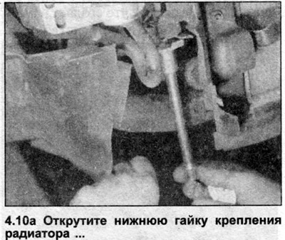
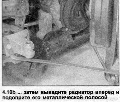
10. The radiator now needs to be separated from its supports on the right side and moved forward to create a working space in front of the engine. To do this, unbolt the brackets on the right side of the radiator, on a 3D engine remove the air ducts, then unbolt the lower mounting nuts and move the right side of the radiator forward. There is a special Audi bracket designed to hold the radiator away from the engine, but a metal strip or a block of wood will work just fine (see illustrations). Alternatively, you can remove the radiator (see Section 2), which will create a much larger workspace.
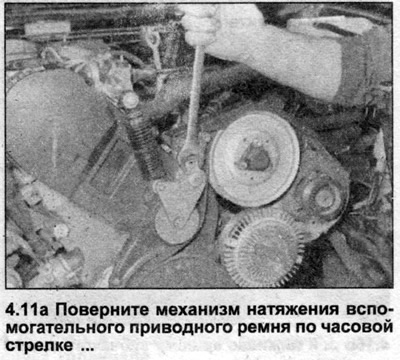
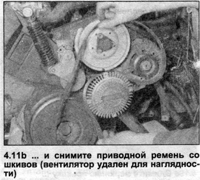
11. Remove the auxiliary drive belt as described in Chapter 7 (see illustrations).
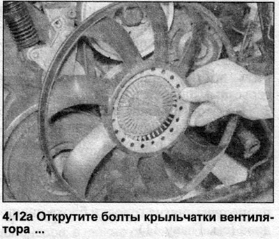
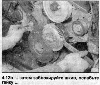
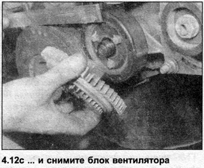
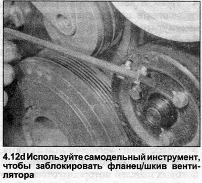
12. Remove the fan unit with the heat-viscous coupling (see Section 2). To do this, first unscrew the impeller mounting bolts, then lock the flange/pulley and unscrew the heat-viscous coupling mounting nut. A homemade locking tool can be made from a metal strip and two bolts (the distance between the hole centers on the flange/pulley is approximately 18 mm) (see illustrations).
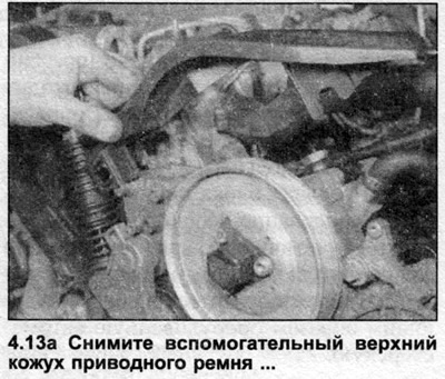
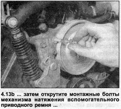
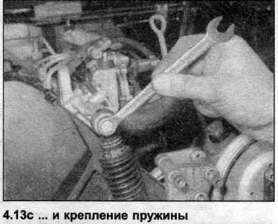
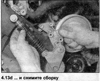
13. Loosen the bolts and remove the upper drive belt cover, tensioner and spring mount, then remove the assembly (see illustrations).
14. Remove the camshaft cover as described in Chapter 8.
15. Remove the bolts securing the cover at the rear of the engine to gain access to the fuel pump drive belt.
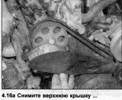
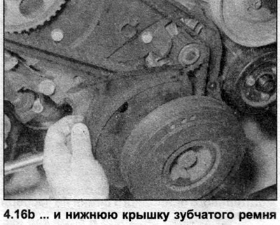
16. Release the spring clips and remove the upper timing belt cover. Remove the bolts and remove the lower timing belt cover (see illustrations).
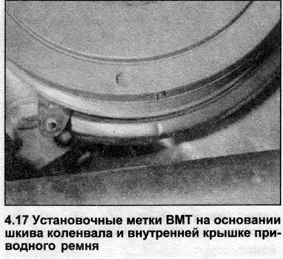
17. Turn the crankshaft and set the engine to TDC as described in Chapter 2. This procedure involves removing the fuel pump drive belt and installing the camshaft locking rod. The TDC marks on the flywheel and on the high-pressure fuel pump should align. The timing marks on the crankshaft pulley base and inner cover should also align (see illustration).
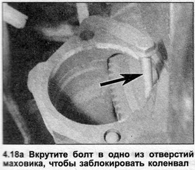
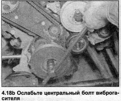
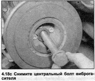
18. Lock the crankshaft and loosen the center bolt of the vibration damper. There is a special Audi tool that fits inside the vibration damper, but on models with a manual transmission, it is enough to select 4th gear and have an assistant press the brake pedal. On models with an automatic transmission, unscrew the torque converter housing cover bolts and have an assistant insert a wide screwdriver between the teeth of the flywheel ring gear. On models with a manual transmission, remove the starter and insert a screwdriver between the teeth of the flywheel ring gear or screw a suitable bolt into one of its holes. Remove the center bolt of the vibration damper (see illustrations). Please note that this bolt should be replaced every time it is removed.
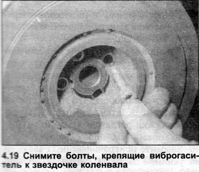
19. Loosen and remove the bolts securing the vibration damper to the crankshaft sprocket, which should still be locked (see illustration).
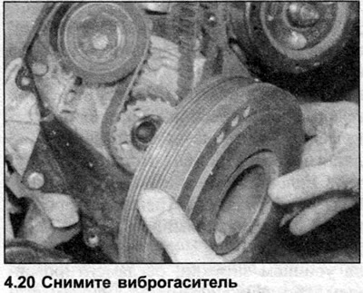
20. Remove the vibration damper from the sprocket (see illustration). If the sprocket moves along with the vibration damper, screw in the two bolts a few turns of the thread and tap them gently to hold the sprocket in the working position.
21. Remove the bolts securing the lower drive belt cover to the cylinder block.
22. Loosen the bolt on the timing belt tensioner mechanism, then turn the mechanism clockwise to reduce the belt tension and tighten the bolt.
23. Mark the drive belt with an arrow indicating the direction of rotation.
Note: If the timing belt is not replaceable, it must be installed so that it rotates in the same direction as before. Do not bend the timing belt, as this may damage it.
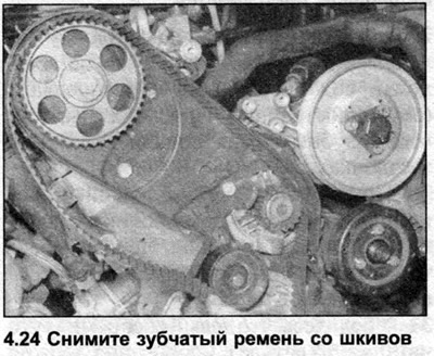
24. Remove the toothed drive belt from the crankshaft, camshaft and water pump sprockets (see illustration).
Inspection
25. If the belt is contaminated with coolant or grease, find the source and correct the cause. Inspect the belt for damage and signs of wear, especially around the drive edges of its teeth. Replace the belt if there is any doubt about its condition; the cost of replacing the belt is insignificant compared to the cost of engine repairs that would be required if the belt broke while driving. The belt should also be replaced if the car has traveled the distance specified by its manufacturers since its installation.
Note: If the timing belt is not installed immediately, it is recommended to attach a warning note to the steering wheel to prevent accidental engine starting.
Installation
26. Make sure that the crankshaft and camshaft are still at TDC (see Chapter 2).
27. Referring to Chapter 6, loosen the camshaft sprocket bolt by half a turn. Gently knock the sprocket off the camshaft cone by carefully inserting a soft metal drift through the hole in the inner timing belt cover.
28. Route the toothed drive belt loosely over the crankshaft sprocket (see illustration).
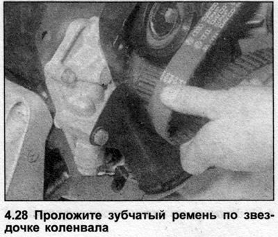
Warning: Orient the belt according to the direction of rotation marks made before removing it.
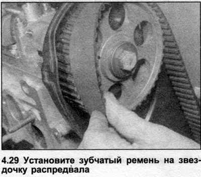
29. Install the belt onto the crankshaft sprocket, then install it onto the water pump and camshaft sprockets (see illustration). Make sure the belt teeth fit into the grooves on the sprockets.
30. Pass the belt with the flat side over the idler pulley and the tensioner pulley. Do not bend or twist the belt during installation.
31. Make sure that the left side of the belt is tight, i.e. all the slack should be in the part of the belt that passes over the tensioner roller.
32. Tighten the timing belt by turning the tensioner counterclockwise. The tensioner hub has two holes; install two drills in them, insert a suitable lever between them and turn the mechanism. With the correct tension in the middle of the run-off between the camshaft and water pump sprockets, the belt can be twisted with your fingers only by 90°. Tighten the bolt with the tightening force specified Specifications.
33. The tensioner hub has two holes; install two drills in them, insert a suitable lever between them and turn the mechanism. With the correct tension at the middle of the run-off between the camshaft and water pump sprockets, the belt can be twisted with your fingers only by 90°. Tighten the bolt with the tightening force specified in the Specifications.
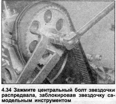
34. Tighten the camshaft sprocket bolt to the specified tightening torque Specifications (see Chapter 6), trying not to bend the locking rod (see illustration).
35. Remove the camshaft locking rod.
36. Turn the crankshaft two full revolutions, then make sure that the TDC timing marks are aligned (see Chapter 2). Make sure that the locking rod can still be inserted into the camshaft groove and check the timing belt tension.
37. Install the lower drive belt cover onto the cylinder block and tighten its bolts.
38. Lubricate the threads and the underside of the head of the crankshaft sprocket center bolt.
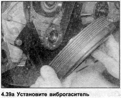
39. Install the vibration damper on the sprocket, then insert the sprocket bolts into it and install a new center bolt and its washer. Lock the crankshaft in the same way as when removing the vibration damper, then tighten the bolts to the specified tightening torque Specifications (see illustrations).
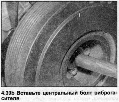
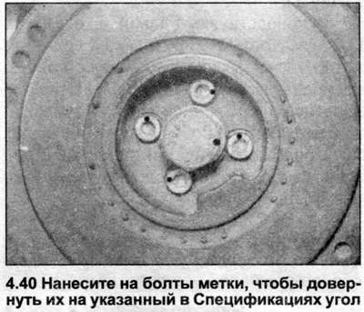
40. Tighten the sprocket center bolt to the specified tightening torque Specifications (see illustration).
41. Install the fuel pump drive belt (see Chapters 2 and 5), then install the belt cover and tighten the bolts.
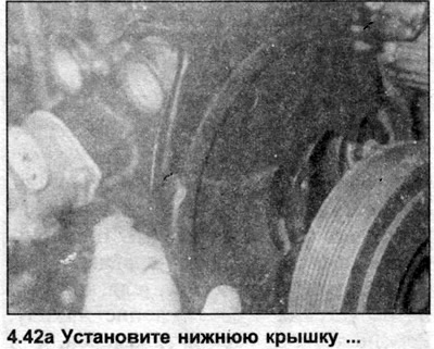
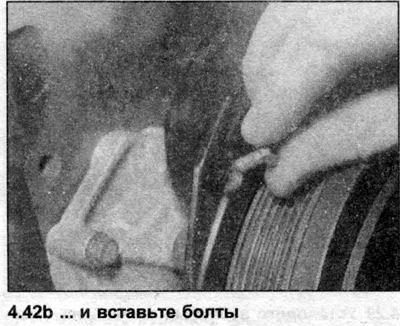
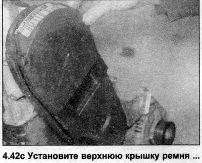
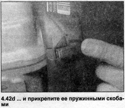
42. Install the lower timing belt cover, then install its upper cover and secure it with spring clips (see illustrations).
43. Install the camshaft cover see. Chapter 8.
44. Install the auxiliary drive belt tensioner, then install the belt itself (see Chapter 7).
45. Install the fan unit as described in Section 2.
46. Install the radiator, brackets and air ducts and tighten the bolts.
47. Install the cross member and hood lock and tighten the bolts.
48. Install the headlights as described in Section 12.
49. Install the front bumper (Section 11).
50. Install the lower engine compartment shield and lower the vehicle to the ground.
51. Connect the negative cable to the battery.
52. If the radiator has been removed, top up the cooling system.