
Table of contents: Removal ↓ Installation ↓
Auxiliary Drive Belt. 4-Cylinder Diesel Engine
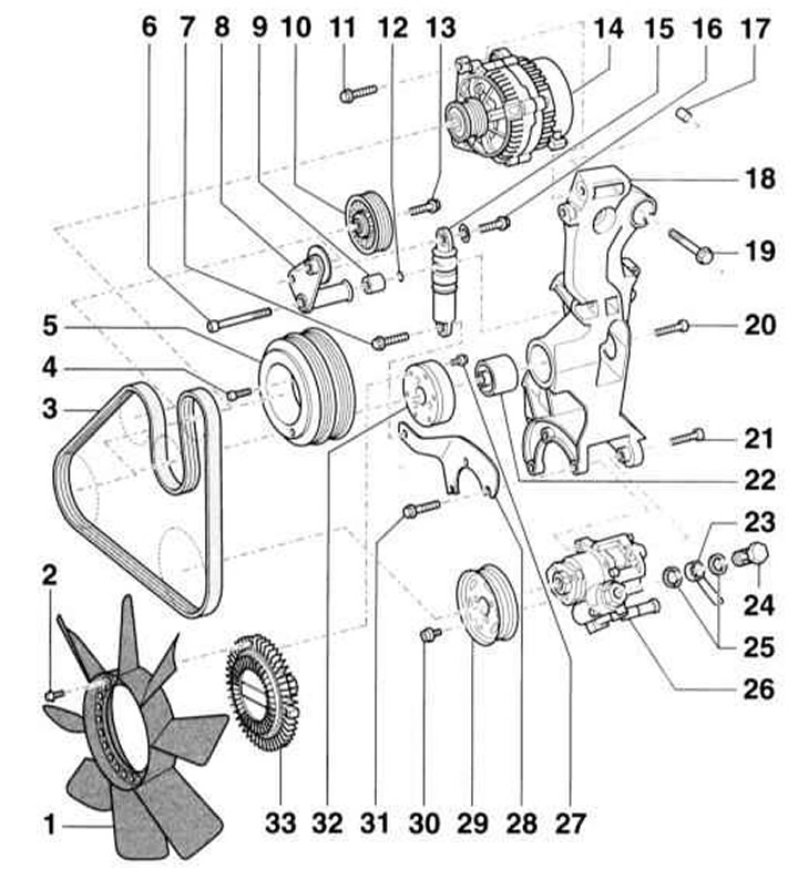
- 1 — Fan impeller with viscous coupling
- 2 — Screw*, 10 Nm
- 3 - V-belt
- 4 — Screw*, 10 Nm + 90°
- 5 — Crankshaft pulley (torsional vibration damper)
- C - rubber cover. Installation is possible only in one position.
- 6 - Screw, 25 Nm. When installing, insert the sealing ring (12)
- 7 - Screw, 25 Nm
- 8 — Tension roller lever
- 9 — Spacer sleeve. Observe the installation position. Install the sealing ring (12)
- 10 — Tension roller
- 11 - Bolt, 25 Nm
- 12 — O-ring. Replace if damaged
- 13 — Bolt*, 25 Nm
- 14 — Generator
- 15 — V-belt tensioner
- 16 - Bolt, 25 Nm
- 17 — Mounting sleeve. Check for proper installation in the holder
- 18 — Holder. When installing, make sure that the right upper bushing is positioned between the holder and the cylinder block
- 19 - Bolt, 45 Nm. Observe the tightening sequence.
- 20 - Bolt, 45 Nm
- 21 - Bolt, 25 Nm
- 22 — Support for fan with viscous coupling
- 23 — Pressure pipeline
- 24 - Hollow bolt, 50 Nm
- 25 — Sealing rings*
- 26 — Power steering pump
- 27 — Bolt with serrated flange*, 28 Nm
- 28 — Tension element holder
- 29 — Power steering pump pulley. To loosen, hold with a mandrel
- 30 - Bolt, 25 Nm
- 31 - Bolt, 25 Nm
- 32 — Fan pulley with viscous coupling
- 33 — Viscous coupling
*) be sure to replace.
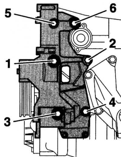
Tightening order of the holder bolts
The bolts of the holder 18 are tightened in sequence from 1 to 6 in 2 steps.
- 1 reception: Bolts 1 through 6 - tighten by hand.
- 2nd reception: Bolts (1) to (6) - torque 45 Nm.
Removal
1. Remove the lower engine compartment cover, refer to Section Removal and installation the upper engine cover/lower engine compartment protection/subframe.
2. Mark the direction of rotation on the V-belt with chalk or a felt-tip pen.
Caution: Reversing the direction of rotation of a belt that has been in use may cause it to break.
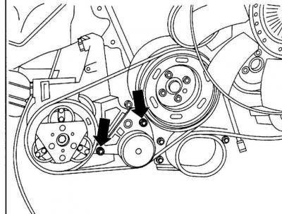
3. Remove the bolts securing the compressor V-belt tension roller (arrows in the accompanying illustration) and thus loosen the belt.
4. Remove the compressor V-belt.
5. Remove the upper air duct in the front right side of the engine compartment, refer to Section Removal and installation the upper engine cover/lower engine compartment protection/subframe.
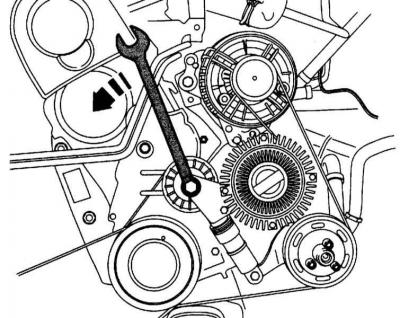
6. Tilt the V-belt tensioner in the direction of the arrow in the accompanying illustration to loosen the belt.

7. Remove the V-belt and relieve the tensioner.
Installation
1. Place the V-belt (A) on the crankshaft pulley (1), power steering pump pulley (2), tensioner pulley (3) and viscous fan pulley (4).
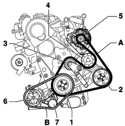
2. Tilt the V-belt tensioner in the direction of the arrow.
3. Lastly, place the V-belt on the generator pulley (5) and relieve the tensioner.
4. Place the V-belt (B) on the crankshaft pulley (1), compressor (6) and tensioner (7).
5. Install the torque wrench (C), as shown in the accompanying illustration, onto the hexagon of the tension roller (1) and tighten the tension roller to a torque of 30Nm.

6. In this position, tighten the screws (2) to the torque 20Nm.
7. Start the engine and visually check the operation of the belt. Pay attention to the correct position of the belt on the pulleys.