
Cylinder head. Diesel engine
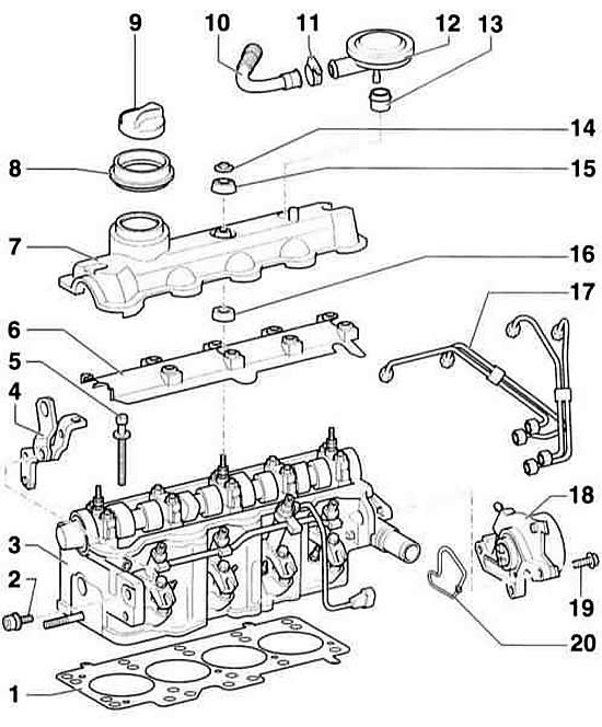
- 1 cylinder head gasket. Pay attention to the marking.
- 2 bolt, 20 Nm
- 3 cylinder head. Not subject to processing.
- 4 eyelets
- 5 Cylinder head mounting bolt. Must be replaced. Bolts are tightened in the sequence corresponding to a 4-cylinder petrol engine
- 6 oil separator
- 7 cylinder head cover. The seal is vulcanized. If damaged, the entire cylinder head cover must be replaced.
- 8 case
- 9 oil filler hole cover. Replace the seal if the seal is damaged.
- 10 to suction hose
- 11 clamp
- 12 pressure regulating valve
- 13 seal. Replace if damaged.
- 14 flange nut, 10 Nm. Lubricate the mating surface if the nut does not reach the stop
- 15 Upper sealing washer. Replace if damaged.
- 16 lower sealing cone
- 17 fuel lines. Fuel lines must be replaced as a set. Do not change the shape of the fuel lines. Tightening torque 25 Nm.
- 18 vacuum pump. For brake booster.
- 19 bolt, 20 Nm
- 20 seal. Must be replaced.
Removal
Warning: Operations and instructions that apply to all engines are given in the section for 4-cylinder petrol engines. This subsection describes only the differences that apply to the diesel engine.
1. Remove the V-belt, refer to subsection Removal and installation the V-belt.
2. Disconnect the electrical wires from the stop device and spark plugs.
3. Clean the fuel lines at the high-pressure fuel pump connections with a cold cleaner and disconnect them. Close the holes with caps.
Warning: Wipe up any leaked engine oil with a rag. Disconnect the oil supply and return lines at the turbocharger. Cover the lines with polyethylene and rubber rings to prevent dirt from getting in.
4. Disconnect the oil feed line to the turbocharger at the holders and the oil filter holder.
5. Loosen the mounting bolts and remove the coolant pipe holder. Remove the pipe.
Warning: Wipe off any leaked diesel fuel with a rag. Disconnect the fuel hoses (arrows) of the high-pressure fuel pump. At the same time, loosen the clamps with pliers, for example, HAZET 798–5. Cover the pipes with polyethylene and rubber rings to protect them from dirt.
6. Disconnect connector –2– of the pressure/temperature sensor at the suction pipe.
7. Disconnect the air supply pipe –1– from the cylinder head.
8. Remove the upper timing belt cover.
9. Remove the two timing belt cover mounting bolts at the rear on both sides of the cylinder head.
10. Turn the engine to TDC and remove the timing belt from the camshaft pulley, refer to subsection Setting the piston of the first cylinder to TDC.
11. Remove the camshaft timing belt pulley, refer to subsection Removal and installation the timing belt.
12. Completely loosen the tension roller nut.

13. The diesel engine has cylinder head mounting bolts with internal splines. Therefore, to unscrew them, a special key is required, for example, HAZET 990 Sig–12. Unscrew the bolts in the reverse order of their numbering, i.e. from 10 to 1.
14. With the help of assistants, remove the cylinder head from the side of the toothed belt protective cover and at the same time remove the tension roller.
Installation
1. Diesel engine cylinder heads cannot be treated.
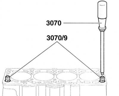
2. To center the cylinder head, use a 3070 screwdriver to screw the AUDI–3070/9 guide pins into the outer holes of the mounting bolts. Note: If the specified pins are not available, old cylinder head mounting bolts with cut off heads can be used instead. To unscrew the pins obtained in this way, it is recommended to make slots on the bottom for the screwdriver.
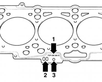
3. Depending on the piston thickness excess, different cylinder head gaskets are installed. When replacing a gasket, pay attention to its marking and use a new gasket only with the same marking. Arrow –1–: Spare part number, arrow –2–: Control code (don't pay attention), arrow –3–: = marking (holes).
4. If new pistons are installed, check the piston overrun and apply a new gasket accordingly (work of the service station).
5. With the help of an assistant, insert the cylinder head into the timing belt guard and at the same time fit the tension roller.
Caution: When installing the cylinder head, do not bend the exhaust manifold heat shield on the rear gasket ears.
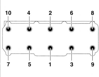
6. The cylinder head mounting bolts are tightened in four stages in sequence from 1 to 10. Tightening torques are given in the Specifications.