
Diesel engines
1. Disconnect the negative (-) battery terminal.
2. Remove the two-piece engine splash guard.
3. Remove the hood.
4. Drain the coolant into a suitable container.
5. Disconnect the electrical wires from the radiator fans.
6. Disconnect the radiator fan thermal switch plug.
7. Unscrew the radiator fan box mounting bolts and remove it from the engine compartment by pushing it upwards.
8. Disconnect all hoses from the radiator on a car with air conditioning, and remove the radiator fan box from the engine compartment by pushing it to the left and up.
TDI engines only
9. Disconnect the three plugs located behind the brake booster: the black eight-pin plug of the high-pressure fuel pump, the black three-pin plug of the engine speed sensor, and the brown two-pin plug of the injector needle stroke sensor.
10. Disconnect the plug holders.
11. Place the wires and plugs away from the work area.
12. Disconnect the power supply wire plugs of the injection advance solenoid valve and the fuel cut-off valve (located behind the fuel pump), glow plugs, coolant temperature sensor on the outlet pipe.
TD engines only
13. Disconnect the power supply wire plug of the fuel cut-off valve and the partial load sensor of the high-pressure fuel pump, as well as the electric water pump.
14. Disconnect the glow plug power supply wires of the fourth cylinder.
15. Pull out the wire harness by pushing it back and set it aside from the work area.
16. Cut the transmission wire harness clamp.
17. Disconnect the gas cable and the cold engine start accelerator cable from the high-pressure fuel pump.
18. All engines: Disconnect the oil pressure sensor and coolant temperature sensor connectors at the outlet pipe.
19. Disconnect the coolant supply hoses to the heater radiator located near the rear wall of the engine compartment.
20. Disconnect the hoses from the fuel filter.
21. Disconnect the hose from the brake booster.
22. Disconnect the coolant hose located on the left side of the engine.
23. Remove the hose from the EGR valve.
24. Disconnect the air supply hose to the turbocharger or to the air volume/mass flow meter from the air filter housing.
TD engines only
25. Disconnect the coolant supply hose from the electric water pump.
26. Release the six retaining clips on the air filter housing and remove the top and replaceable filter element.
27. Mark the oil supply and return hoses on the oil radiator and disconnect them from the oil filter.
28. Secure the oil lines in the engine compartment to prevent oil leakage.
29. Disconnect the coolant line from the electric water pump, located on the right side of the engine, and from the heater radiator hoses. To do this, remove the two bolts on the transmission-to-engine mounting flange and disconnect the hose mount on the rear of the cylinder head.
TDI engines only
30. Disconnect the air supply hose from the turbocharger.
31. Disconnect the air volume/mass flow meter plug.
32. Disconnect the small diameter hoses from the rear of the air cleaner housing.
33. Press the clamps on the air filter housing and remove the top of the filter together with the air volume/mass flow meter and the replaceable filter element.
34. Disconnect the inlet air temperature sensor plug.
35. Disconnect the air supply hose to the intercooler on the turbocharger.
36. Disconnect the hose from the boost pressure regulator chamber.
37. Disconnect the thin hose on the front of the turbocharger.
38. Disconnect the coolant hose from the oil radiator.
39. Disconnect the coolant line from the left side of the engine.
All engines
40. Disconnect the lower part of the air filter housing.
41. Unscrew the four 12 nuts on the flange connection of the inlet pipe and turbocharger.
42. Unscrew the nuts securing the left and right engine mounts.
43. Remove the upper gearbox-to-engine mounting bolts. Loosen one bolt, but do not remove it.
44. Disconnect the wire from the generator.
45. Loosen the clamps and disconnect the wires from the starter.
46. Remove the starter.
On vehicles with air conditioning, remove the upper coolant circulation hose holders.
Caution: Be careful. Hoses are sensitive to kinking. Do not open the coolant circulation circuit!
47. Remove the V-belt.
48. Remove the lower coolant circulation hose holders.
49. Remove the generator.
50. Disconnect the air conditioning compressor plug.
51. Unscrew the air conditioning compressor mounting bolts and remove it. Without disconnecting the coolant hoses, lower the compressor down and secure it to the body.
On cars with an automatic transmission, unscrew the three bolts securing the torque converter in the hole of the removed starter. To do this, turn the engine by ⅓ of a turn each time.
52. Remove the lower bolts on the gearbox mounting flange to the engine.
53. Remove the right drive shaft protective cover.
54. Remove the power steering pump and secure it in the engine compartment without disconnecting the pipes.
55. Disconnect the exhaust system mounting bracket from the gearbox housing.
56. Disconnect the front engine mount from the engine and from the cross member.
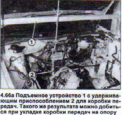
57. Secure the gearbox to a support stand or use the AUDI 10-222A lifting device with a 3147 gearbox holding device (see illustration 4.66a).
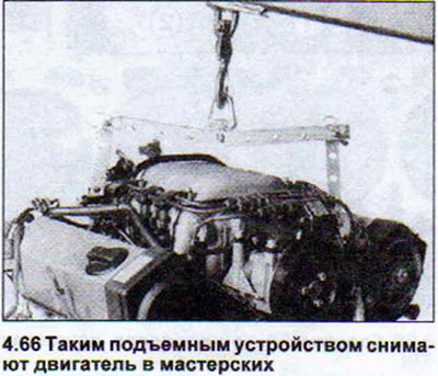
58. Place the hoist cable through the engine lugs and lift the power unit.
59. Place a support under the gearbox, taking into account that the power unit is raised.
60. Remove the remaining bolt securing the gearbox to the engine.
61. Press the gearbox away from the engine and remove the engine from the engine compartment.
For vehicles with automatic transmission, after removing the engine, secure the torque converter in the transmission to prevent it from falling out.
Petrol engines
The procedure for removing all types of gasoline engines is generally the same and is largely identical to the procedure for removing diesel engines. Only the basic steps are given below.
62. First remove all parts that will prevent the engine from being removed from the engine compartment. These include: the hood, engine splash guard, air filter, battery, and, if necessary, the radiator.
63. Label the connecting wires and hoses appropriately so that they are not mixed up when installing the engine in place.
64. Make sure you have the radio security code written down before disconnecting the battery.
65. Switch off the ignition before disconnecting the battery. Failure to do so may damage the vehicle's electronic control units.
66. Disconnect the gearbox from the engine only before removing it from the engine compartment. To do this, install a suitable support under the gearbox and disconnect the power unit, or lift it slightly and secure the gearbox so that it does not fall after disconnecting from the engine. In workshops, a special device is used for this, resting on the edges of the wing mounts (see illustrations).
Installation
When installing the engine in place, pay special attention to the following points:
67. Install the alignment bushings for the engine and gearbox if there are none on the cylinder block.
68. Lubricate the clutch release bearing and the gear ring of the gearbox input shaft with a thin layer of G 000100 grease. Do not lubricate the release bearing guide sleeve.
69. Install the engine in place without stress. To do this, before finally tightening the engine mount bolts, rock it from side to side.
70. Secure the exhaust pipe without causing any stress.
Attention! Be sure to replace the self-locking nuts with new ones.
(The original publication in its entirety is posted on the website: AudiManual)