
Table of contents: Removal ↓ Installation ↓
Accessory Drive Belt Routing Diagram. 4-Cylinder Gasoline Engine
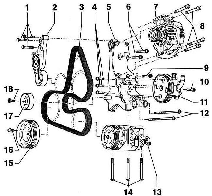
- 1 - Bolts, 25 Nm
- 2 - Semi-automatic toothed belt tensioner
- 3 - V-belt
- 4 - Bolts, 25 Nm
- 5 — Generator, power steering pump and air conditioning compressor holder
- 6 - Bolts, 40 Nm
- 7 — Generator
- 8 - Screws, 20 Nm
- 9 - Screw, 40 Nm
- 10 - Bolt, 20 Nm
- 11 — Power steering pump
- 12 - Bolts, 40 Nm
- 13 — Air conditioning compressor. When installing, pay attention to the guide bushings in the holes
- 14 - Bolts, 20 Nm
- 15 — Crankshaft wheel. Installation is possible in only one position: the wheel mounting hole must be located above the protrusion on the toothed belt wheel
- 16 - Flange bolts, 10 Nm + 90°. Be sure to replace. Note: Only original bolts may be used
- 17 — Guide roller. Fastened to the generator holder, power steering pump and air conditioning compressor
- 18 - Special guide roller bolt, 25 Nm
Removal
1. Mark the direction of rotation on the V-belt with chalk or a felt-tip pen.
Caution: Changing the direction of rotation of a belt that has already been in use may cause it to break.
2. Tilt the tensioner to loosen the V-belt in the direction of the arrow in the accompanying illustration A.
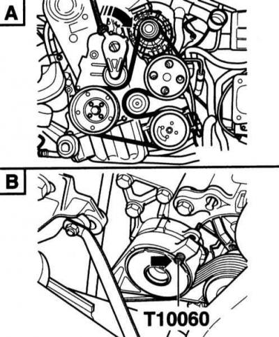
3. Fix the tensioner with the T10060 mandrel (arrow on the accompanying illustration B).
4. Remove the V-belt.
Installation
1. Check if all units are securely installed (generator, compressor, pump).
2. Put on the V-belt according to the direction of rotation mark.
3. For vehicles with air conditioning, place the belt on the compressor last.
4. Tilt the tensioner slightly in the direction of the arrow (B) and remove the locking pin (A). Then slowly return the tensioner to its original position. At the same time, check whether the belt is correctly positioned on the pulleys.
5. Start the engine and let it idle. Visually inspect the belt.