
Table of contents: Removal ↓ Installation ↓
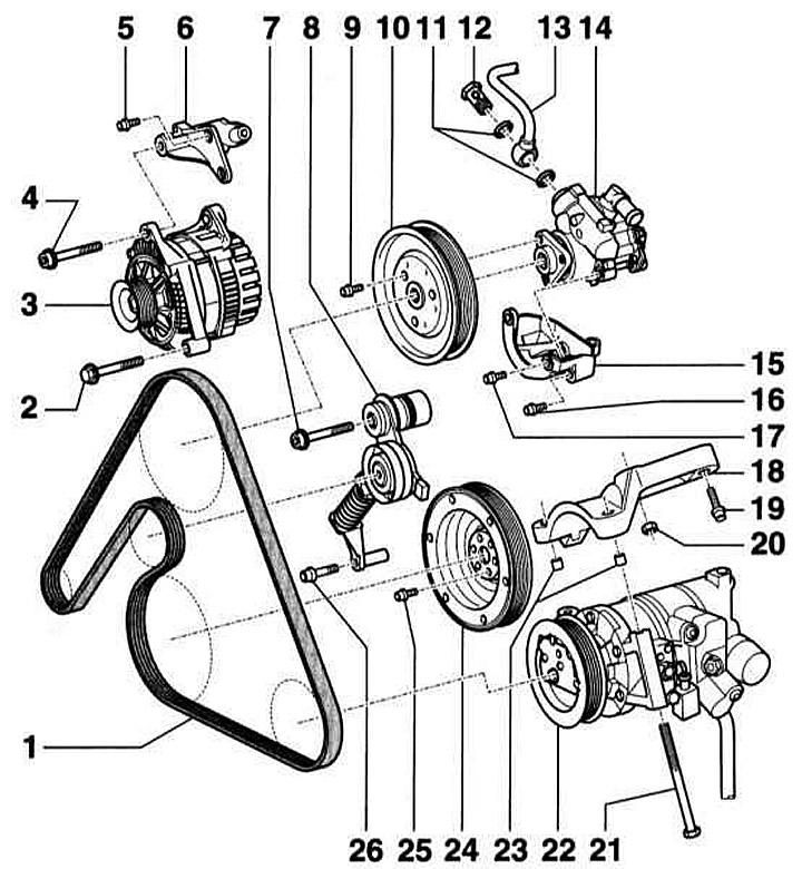
- 1 - V-belt
- 2 - Bolt, 23 Nm
- 3 - Generator
- 4 - Bolt, 45 Nm
- 5 - Bolt, 23 Nm
- 6 — Generator holder
- 7 - Screw, 40 Nm
- 8 - Tensioning device
- 9 - Screw, 23 Nm
- 10 — Power steering pump pulley
- 11 — O-ring. Be sure to replace it
- 12 - Hollow bolt, 47 Nm
- 13 — Pressure line for power steering pump
- 14 — Power steering pump
- 15 — Pump holder
- 16 - Bolt, 23 Nm
- 17 - Bolt, 23 Nm
- 18 — Air conditioning compressor holder
- 19 - Bolt, 23 Nm
- 20 - Nut, 23 Nm
- 21 - Bolt, 25 Nm
- 22 — Compressor. Attention: Do not unscrew/disconnect the coolant pipes. After removing the compressor, secure it to the body with wire. Do not hang it by the pipes
- 23 — Compressor bushings
- 24 — Crankshaft pulley (torsional vibration damper)
- Depending on the year of manufacture, with or without a thrust washer between the torsional vibration damper (crankshaft pulley) and a toothed belt wheel.
- 25 - Bolt, 23 Nm
- 26 - Bolt, 23 Nm
Belt routing diagram. 6-cylinder gasoline engine
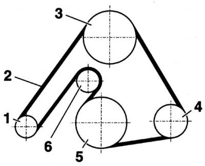
- 1 - Generator
- 2 - V-belt
- 3 — Power steering pump
- 4 — Compressor
- 5 — Crankshaft
- 6 — Tension roller
Removal
1. Remove all upper engine covers. Disconnect the EGR solenoid valve and remove the front right air duct.
2. Mark the direction of rotation on the V-belt with chalk or a felt-tip pen.
Changing the direction of rotation of a belt that has already been in use may cause it to break.
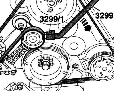
3. Loosen the V-belt and remove it. To do this, tilt the tensioner with a suitable lever, e.g. 3299/3299/1, in the direction of rotation.
Installation
1. Installation is performed in the reverse order of removal. In this case, first put the V-belt on the crankshaft pulley and then on the tension roller.
(Content source: the specified website «audimanual.ru»)