
Table of contents: Removal ↓ Setting and adjusting tension ↓
Removal
Warning: Before removing, mark the direction of rotation of the timing belt with chalk, marker or paint. If a used timing belt is installed with the opposite direction, it will cause damage to the belt.
Note
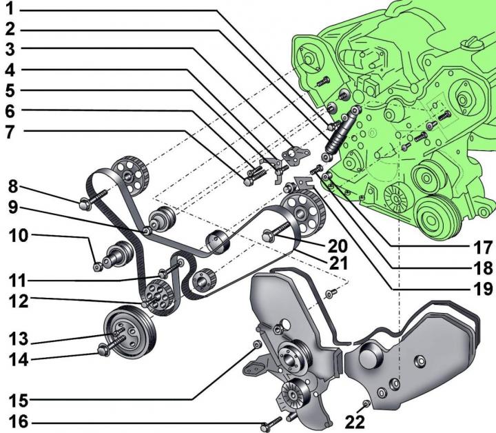
Fig. 3.2–17. Toothed belt: 1 – bolt, 25 Nm; 2 – shock absorber; 3 – tension lever; 4 – TDC indicator; 5 – axle bolt; 6 – axle bolt; 7 – bolt, 25 Nm; 8 – bolt with washer, 55 Nm; 9 – bolt, 25 Nm; 10 – bolt, 25 Nm; 11 – bolt, 25 Nm; 12 – bolt, 80 Nm; 13 – bolt, 25 Nm; 14 – central bolt; 15 – flange nut, 10 Nm; 16 – bolt, 45 Nm; 17 – Sliding block; 18 – bolt, 10 Nm; 19 – tension mechanism lever; 20 – bolt, 45 Nm; 21 – toothed belt; 22 – flange nut, 10 Nm
When screwing in with special tool 2079, the tightening torque of the central bolt 14 (Fig. 3.2–17) is 350 N·m; without special tool 2079 – 450 N·m.
Before disconnecting the battery, find out if you have a radio activation code.
All clamps and straps that are damaged or cut during engine removal must be replaced with new ones when reassembling the engine.
The battery is located under the luggage compartment floor.
Turn off the ignition and disconnect the ground wire from the battery.
By turning the engine crankshaft in the direction of its working rotation using the crankshaft pulley mounting bolt, set the piston of the first cylinder to the top dead center (TDC).
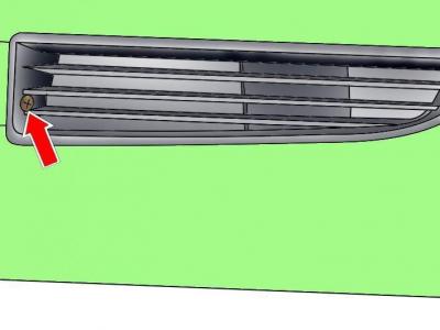
Fig. 3.2–1. Location of the screw securing the left ventilation grille
Remove the screw securing the left bumper ventilation grille (at the same time the right grid is also freed) and remove the grates (see Fig. 3.2–1).
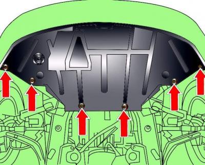
Fig. 3.2–2. Location of the engine compartment lower mudguard mounting screws
Remove the screws and remove the lower engine compartment splash guard (see Fig. 3.2–2)
Open the tap at the base of the radiator, attach a 12 mm diameter hose to the tap and drain the coolant from the radiator.

Fig. 3.2–18. Loosening the tension of the poly V-belt
Loosen the tension of the poly V-belt by using a hex wrench to turn the tensioning mechanism upwards (Fig. 3.2–18).
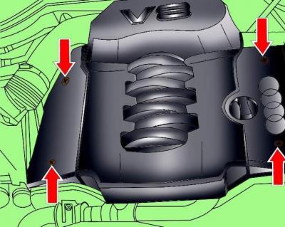
Fig. 3.2–3. Location of engine casing mounting screws
Remove the screws and remove the engine casing (see Fig. 3.2–3).
Release the coolant hose clamp from the right timing belt cover.
Loosen the clamps and remove the air intake pipe connecting the air filter and the throttle body.
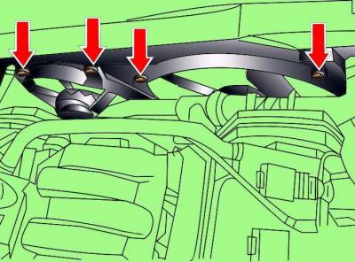
Fig. 3.2–19. Location of radiator fan shroud mounting bolts
Remove the bolts and lift the radiator fan shroud upwards (Fig. 3.2–19). Disconnect the electrical connectors from the radiator fan motor.
If a viscous coupling radiator fan is installed, remove it.
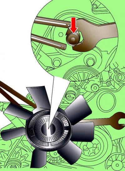
Fig. 3.2–20. Removing the radiator fan mounting bolt
While holding the radiator fan pulley from turning with a special key 3212, use a regular key to unscrew the pulley mounting bolt. Keep in mind that the bolt has a left-hand thread, so to unscrew it, you need to turn it clockwise (Fig. 3.2–20).
Lift the radiator fan up and remove it from the vehicle.
Unscrew the front right engine mount.
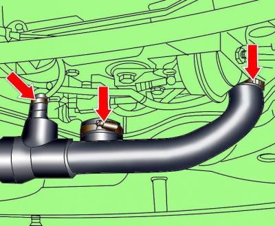
Fig. 3.2–21. Location of clamps for fastening the cooling system hoses to the engine
Loosen the clamps and disconnect the cooling system hoses from the engine (Fig. 3.2–21).
Loosen the clamp, disconnect the coolant hose from the top of the radiator and turn it clockwise.
By turning the engine crankshaft in the direction of its working rotation using the crankshaft pulley mounting bolt, set the piston of the first cylinder to TDC.
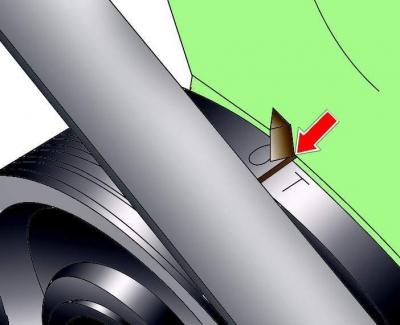
Fig. 3.2–22. Aligning the mark on the crankshaft pulley with the pointer on the casing
Check: the mark on the crankshaft pulley should align with the pointer on the casing (Fig. 3.2–22).

Fig. 3.2–23. Using special device 3197 to fix the crankshaft pulley from turning
Using special tool 3197 (Fig. 3.2–23), secure the crankshaft pulley from turning and unscrew it one turn (but don't unscrew it completely) crankshaft pulley mounting bolt.
Unscrew the sensor housing at the rear of the right cylinder head.

Fig. 3.2–24. Location of screws securing the left timing belt cover
Unscrew the bolts and remove the left timing belt cover (Fig. 3.2–24).
Remove the right timing belt cover secured to the poly V-belt pulley by removing the pulley.
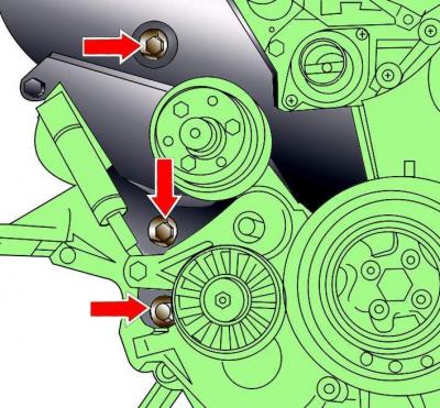
Fig. 3.2–25. Location of the bolts securing the right timing belt cover
Remove the six screws securing the right timing belt cover and remove the cover (Fig. 3.2–25).
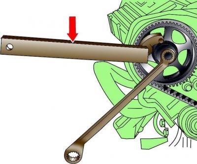
Fig. 3.2–26. Using special tool 3036 to prevent the camshaft pulley from turning
Alternately, using special device 3036 (Fig. 3.2–26), fix the camshaft pulley from turning and unscrew it three turns (but don't unscrew it completely) camshaft pulley mounting bolt.
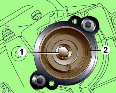
Fig. 3.2–27. Location of the bolt (1) securing the sensor rotor (2) on the left cylinder head
Remove the sensor rotor from the left cylinder head (Fig. 3.2–27).
Cover the camshaft projections with special cups with flanges (special device 3341).
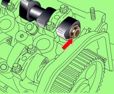
Fig. 3.2–28. Location of the hexagonal protrusion for turning the camshaft
Turn the camshaft by the hexagonal protrusion at the end of the shaft after removing the cylinder head cover (Fig. 3.2–28).
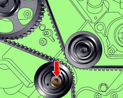
Fig. 3.2–29. Location of the timing belt tension roller fastening nut
Loosen the tension of the toothed belt by loosening the tension roller mounting nut and turning the roller downwards (Fig. 3.2–29).
Manually compress the timing belt tensioner damper.
Using chalk, marker or paint, mark the direction of rotation of the timing belt.
Remove the timing belt from the camshaft pulleys.
To turn the camshaft pulleys, remove them from the seat cones by tapping the back of the pulleys with a plastic or wooden hammer.
Remove the four vibration damper pulley mounting bolts.
Remove the crankshaft pulley mounting bolt.
Take it off vibration damper, while the crankshaft timing belt pulley must remain in place.
Remove the timing belt.
Do not turn the engine crankshaft with the timing belt removed, as the pistons may hit the valves.
Warnings: 1. Do not twist or bend the timing belt. Prevent oil, coolant or fuel from coming into contact with the timing belt.
If the timing belt teeth have crumbled, the distributor, water pump, oil pump, or camshaft may be seized.
2. The timing belt can break on a running engine as a result of the pistons hitting the valves, which can cause the valves to bend. Check the valve clearances. The clearances on bent valves will be significantly larger than required.
If the outer surface of the timing belt is significantly worn or delaminated, check the condition of the idler pulley raceway.
If only one side of the belt is worn or damaged, check the timing belt guide and timing belt pulley alignment.
If there are any defects on the timing belt, it must be replaced.
Setting and adjusting tension
Install the timing belt onto the crankshaft pulley.
Install vibration damper.
Screw in and hand tighten the four vibration damper mounting bolts.
Apply a thin layer of engine oil to the threads and the bearing surface of the bolt head and screw in the crankshaft pulley mounting bolt. To prevent the pulley from turning, secure it with a special device.
Make sure that the camshaft timing belt pulleys rotate freely on the cones, i.e. the pulley mounting bolts are unscrewed one turn.
Install the timing belt on all pulleys, including the water pump pulley.
Tighten the timing belt tension roller mounting nut so that the roller eccentric can still be turned.
Tighten the four vibration damper mounting bolts.
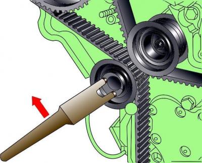
Fig. 3.2–30. Adjusting the timing belt tension
Adjust the tension of the toothed belt by turning the tension roller eccentric clockwise using special tool V–159 until the required shock absorber length is achieved (Fig. 3.2–30 and 3.2–31).
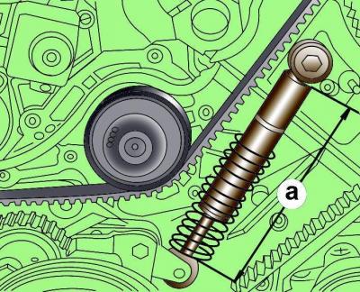
Fig. 3.2–31. Measuring the length of the timing belt shock absorber
The length of the timing belt shock absorber on a cold engine should be 136–139 mm, on a hot engine – 126–129 mm.
Remove the special cups with flanges that cover the camshaft protrusions.
Install the sensor rotor to the rear of the cylinder head and secure it with the bolt (see Fig. 3.2–27).
Manually turn the engine crankshaft two revolutions.
Further installation is carried out in the reverse order of removal.