
Table of contents: Replacing the seal in the left upper… ↓ Left upper timing chain cover (bTR… ↓ Left upper timing chain cover… ↓ Right upper timing chain cover ↓ Lower timing chain cover ↓
1. Timing chain cover installation details are shown in the illustrations.
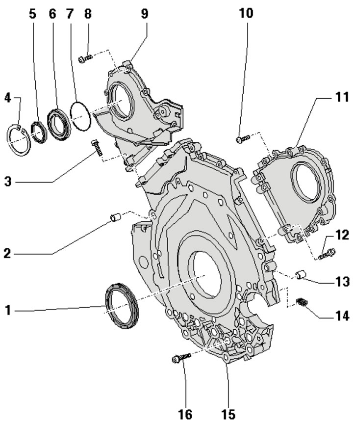
39.1a. Timing chain cover installation details (bTR engine):
1 - Rear crankshaft oil seal;
2, 13 - Centering bushings, 2 pcs.;
3, 8, 10, 12 - Cover fastening bolts 9 and 11, subject to replacement;
4 - Retaining ring;
5 - Gear oil seal;
6 - Oil seal adapter;
7 - O-ring, must be replaced;
9 - Left upper timing chain cover;
11 - Right upper timing chain cover;
14 - Sealing plug, 2 pcs.;
15 - Lower timing chain cover;
16 - Cover fastening bolts 15.
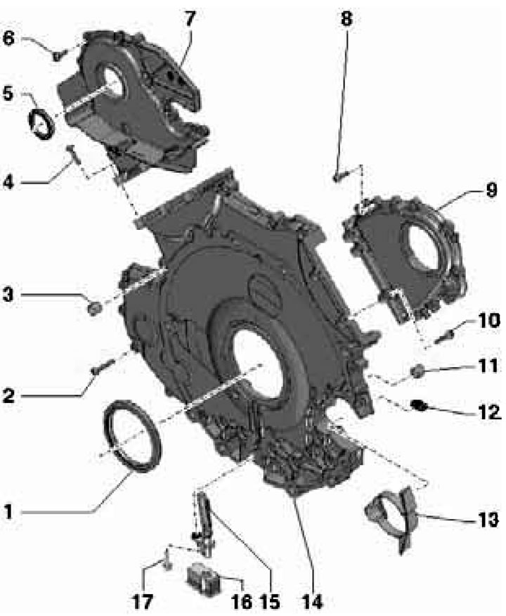
39.1b. Timing chain cover installation details (cCFA/CCFC engines):
1 - Rear crankshaft oil seal;
2 - Cover mounting bolts 14;
3, 11 - Centering bushings, 2 pcs.;
4, 6, 8, 10 - Cover mounting bolts 7 and 9, subject to replacement;
5 - Gear oil seal;
7 - Left upper timing chain cover;
9 - Right upper timing chain cover;
12 - Sealing plug, 2 pcs.;
13 - Starter housing;
14 - Lower timing chain cover;
15 - SCR sensor;
16 - Crankshaft position sensor cover;
17 - Crankshaft position sensor mounting bolt.
The timing chains are located on the rear of the engine.
Replacing the seal in the left upper chain cover
2. Remove the upper engine cover and the air intake chamber cover (see Section 19 of Chapter 1).
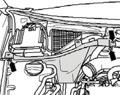
3. Remove the screws (see illustration) and remove the left air intake chamber divider panel.
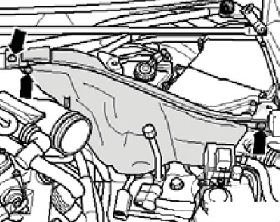
39.3. Fastening the left dividing panel.
4. Remove the fuel injection pump drive toothed belt (see Chapter 4). On the BTR engine, additionally remove the fuel injection pump and its bracket. Holding the camshaft from turning with devices T10172 and T10172/2 (see illustration), unscrew the gear wheel mounting bolt and remove the wheel.
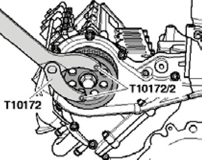
39.4. Removing the drive gear of the fuel injection pump.
5. On the BTR engine, remove the retaining ring (2 in the illustration), remove the adapter (1) of the oil seal and press the oil seal out of the adapter.
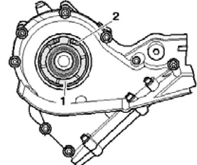
39.5. Retaining ring (2) and adapter (1) of the seal.
6. On CCFA/CCFC engines, remove the oil seal from the chain cover using tool #10-221 (see illustration).
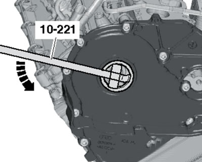
39.6. Removing the oil seal on CCFA/CCFC engines.
7. On the BTR engine, slide on the oil seal (2 in the illustration) onto the adapter (1) using the T10053 tool.
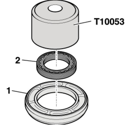
39.7. Installing the oil seal on the BTR engine.
8. On CCFA/CCFC engines, slide the oil seal directly into the chain cover, also using tool T10053.
9. Install the remaining parts in the reverse order of removal.
Left upper timing chain cover (bTR engine)
10. Remove the oil seal from the left upper cover (see subsection above).
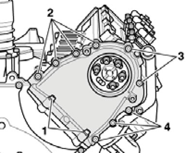
11. Loosen the bolts (1-4 in the illustration) in a diagonal order and carefully remove the lid (it is held in place by sealant).
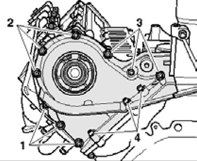
39.11. Left upper timing chain cover fastening bolts.
12. Using a plastic drill brush, remove old sealant from the cover grooves and from the mating surfaces of the covers/cylinder head. At the same time, do not allow dirt to enter the lubrication system. Clean mating surfaces from oil and grease.
Note: After subsequent application of sealant, the lid must be installed within 5 minutes.
13. Apply sealant to the joints of the cylinder head with the lower timing chain cover (see illustration).
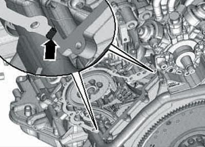
39.13. Sealant at the joints of the cylinder head and the lower timing chain cover.
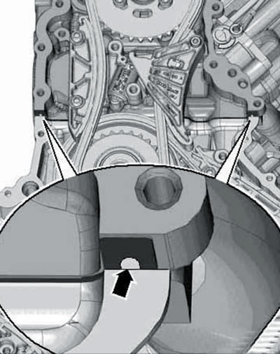
14. Apply sealant into the groove (arrow in the illustration) lids.
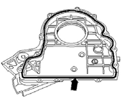
39.14. Scheme for applying sealant to the left upper timing chain cover.
In this case, the sealant should completely fill the groove and protrude from it by 1.5-2.0 mm.
15. Install the cover and tighten the bolts in the following order (see illustration 39.11):
- Bolts (1-3) - with a force of 5 Nm in a diagonal order;
- Bolts (4) - with a force of 8 Nm;
- Bolts (1-3) - with a force of 8 Nm in a diagonal order;
- Bolts (4) - tighten to an angle of 90°;
- Bolts (1-3) - tighten at an angle of 90° in a diagonal order.
16. Install the oil seal (see subsection above).
Left upper timing chain cover (cCFA/CCFC engines)
17. Remove the belt and the drive sprocket of the fuel injection pump (see Chapter 4). Then unscrew the bolt (see illustration) and remove the tension roller together with the support.
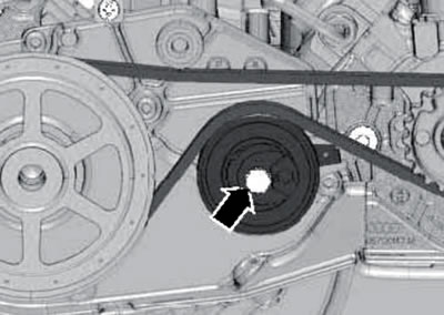
39.17. Tension roller bolt.
18. Loosen the bolts (by analogy with 1-4 in illustration 39.11) in a diagonal order and carefully remove the lid (it is held in place by sealant).
19. Remove the seal from the cover (see the relevant subsection above).
20. Follow the steps described in paragraphs 12-15.
21. Install the seal into the cover. Install the remaining parts.
Right upper timing chain cover
22. Remove the rear right coolant pipe (see Chapter 3) and a vacuum pump (see Chapter 9).
23. Remove ECM No. 2 (2 in illustration 35.30), as described in Chapter 5.
24. Remove the screws (see illustration) and remove the right air intake chamber divider panel.
39.24. Fastening the right dividing panel.
25. Loosen the bolts (by analogy with 1-4 in the illustration) in a diagonal order and carefully remove the lid (it is held in place by sealant).
39.25. Left upper timing chain cover mounting bolts.
26. Perform the actions described in paragraphs 12-14, acting by analogy.
27. Install the cover and tighten the bolts in the following order (see illustration 39.25):
- Bolts (2-4) - with a force of 5 Nm in a diagonal order;
- Bolts (1) - with a force of 8 Nm;
- Bolts (2-4) - with a force of 8 Nm in a diagonal order;
- Bolts (1) - tighten to an angle of 90°;
- Bolts (2-4) - tighten at an angle of 90° in a diagonal order.
28. Install the remaining parts.
Lower timing chain cover
29. Remove the drive disc (see Section 38).
30. Remove the covers of both upper timing chains (see the relevant subsections above).
31. Remove the rear left coolant pipe (see Chapter 3). On the BTR engine, drain the engine oil (see Section 6 of Chapter 1).
32. Remove the bolts (1 in illustration 35.46) and remove the left turbocharger bracket.
33. On CCFA/CCFC engines, disconnect the connector (2 in the illustration) sKR sensor.
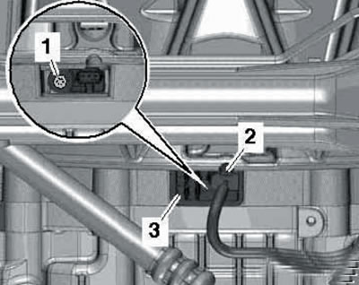
39.33. SKR sensor connector.
34. Loosen the bolts (1-8 in the illustrations) in a diagonal order and carefully remove the lid (it is held in place by sealant).
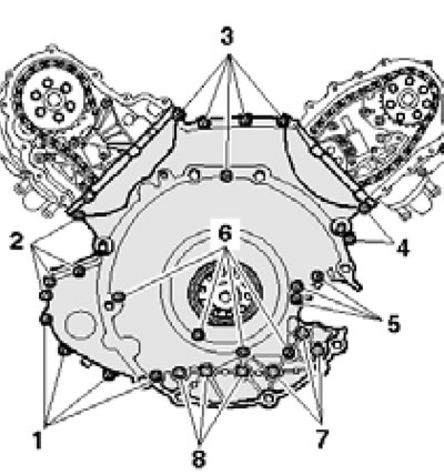
39.34a. Fastening the lower timing chain cover of the BTR engine.
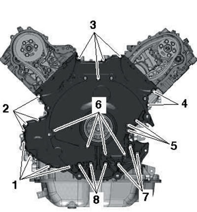
39.34b. Fasteners for the lower timing chain cover of CCFA/CCFC engines.
Remove the rear crankshaft oil seal from the cover (see Section 38).
35. Using a plastic drill brush attachment, remove old sealant from the cover grooves and from the mating surfaces of the covers/cylinder head. At the same time, do not allow dirt to enter the lubrication system. Clean mating surfaces from oil and grease.
Note: After subsequent application of sealant, the lid must be installed within 5 minutes.
36. On CCFA/CCFC engines, remove old sealant from the grooves in the cylinder head gaskets and fill these grooves with fresh sealant.
39.36. Groove in the cylinder head gasket.
Note: When the cylinder heads are installed, only half of the grooves are visible.
37. Install the sealing elements (2 and 5 in the illustration) and apply sealant into the grooves (1 and 4) of the cover.
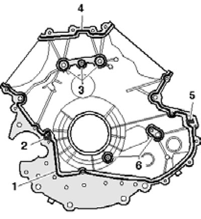
39.37a. BTR engine lower timing chain cover seals.
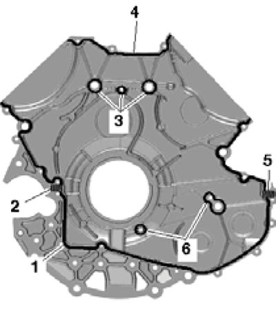
39.37b. Lower timing chain cover seals for CCFA/CCFC engines.
The sealant should completely fill the groove and protrude 1.5-2.0 mm beyond it. Apply 1.5-2.0 mm diameter beads of sealant around the holes (3 and 6), as well as a thin layer of sealant to the sealing elements.
38. Make sure that two centering bushings are present, install the cover and tighten its bolts in the following order (see illustrations 39.37ab):
- Bolts (1-8) - with a force of 5 Nm in a diagonal order, starting from the inner ones and moving outwards;
- Bolts (1-6) - with a force of 9 Nm in a diagonal order, starting from the inner ones and moving outwards;
- Bolts (7 and 8) - with a torque of 22 Nm.
39. Install the oil seal (see subsection above).