
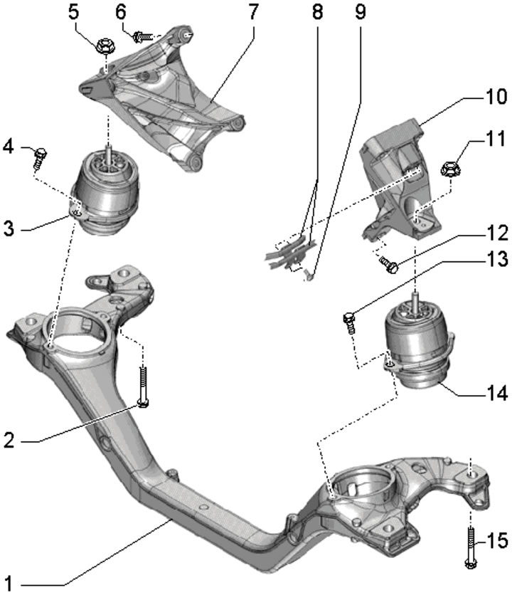
36.1. Engine support and crossmember installation details:
1 - Engine crossmember;
2, 15 - Bolt, subject to replacement, 120 Nm, then tighten to an angle of 180°;
3 - Right engine mount;
4, 13 - Bolt, 60 Nm;
5, 11 - Nut, 75 Nm;
6, 12 - Bolt, 50 Nm, then tighten to an angle of 90°;
7 - Right engine support bracket;
8 - Oil and coolant supply lines;
9 - Bolt, 9 Nm;
10 - Left engine support bracket;
14 - Left engine mount.
Left support
2. On models with air suspension, activate the vehicle jacking mode (see Introduction).
3. Remove the upper engine cover (see Section 19 of Chapter 1), front left wheel and front left wheel arch liner (see Chapter 10).
4. Loosen the clamp (1 in illustration 35.21) and disconnect the air tube from the left air cleaner cover. Disconnect the connector (2) of the MAF sensor No. 2 "G246", release the clips (3) and remove the air cleaner cover.
5. Disconnect the connector (3 in the illustration), unscrew the bolt (1), loosen the clamps (2 and 5) and remove the left air tubes.
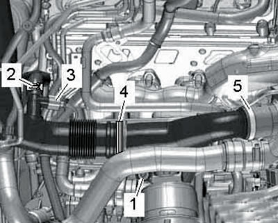
36.5. Connections of the left air tubes.
6. Lift the latch and disconnect the air hose (1 in illustration 35.2a) from the left side of the intercooler. Unscrew the bolt (2) and slightly press the air tube upwards.
7. Loosen the clamp (1 in illustration 35.19) and disconnect the air hose.
8. Give the nut (arrow in the illustration) and unscrew the bolts (1) of the left engine support.
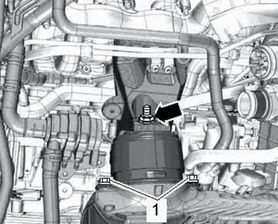
36.8. Support fastening.
9. Remove the hood seal on both sides (see illustration).
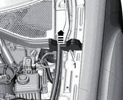
36.9. Hood seal.
10. Install beam No. 10-222A with supports T10-222A/22 and spindle on the flanges of the front wings (1 in the illustration).
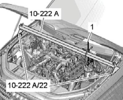
36.10. Hanging the left side of the engine.
Hook the spindle hook onto the rear left engine lifting eye and lift the engine until the bracket is above the left engine mount stud. After this, the support can be removed.
11. Installation is carried out in reverse order.
Right support
12. Remove the generator (see Chapter 5).
13. Unscrew the bolt (1 in illustration 35.49), loosen the clamp (2) and disconnect the right air pipe.
14. Give the nut (arrow in illustration 35.52) and unscrew the bolts (1) of the right engine support.
15. Loosen the bolt (1 in the illustration) and unscrew the bolt (2) with the nut.
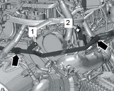
36.15. Fastening of the rear right coolant pipe.
Remove the rear right coolant pipe from the rear right engine lifting eye.
16. Remove the hood seal on both sides (see illustration 36.9).
17. Install beam No. 10-222A with supports T10-222A/22 and spindle on the flanges of the front wings (1 in the illustration).
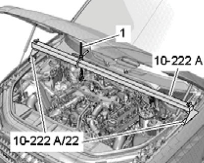
36.17. Hanging the right side of the engine.
Hook the spindle hook onto the rear right engine lifting eye and lift the engine until the bracket is above the left engine mount stud. After this, the support can be removed.
18. Installation is carried out in reverse order.
Crossbar
19. On models with air suspension, activate the vehicle jacking mode (see Introduction).
20. Remove the upper engine cover (see Section 19 of Chapter 1).
21. Disconnect the negative cable from the battery (see Chapter 5).
22. Loosen the bolt (1 in illustration 36.15) and unscrew the bolt (2) with the nut. Remove the rear right coolant pipe from the rear right engine lifting eye.
23. Remove the hood seal on both sides (see illustration 36.9).
24. Install beam No. 10-222A with T10-222A/22 supports and two spindles on the flanges of the front wings (1 in illustrations 36.10 and 36.17). Hook the spindle hooks into the rear lifting eyes and remove both engine mounts (see subsections above).
25. Remove the anti-roll bar (see Chapter 9).
26. Remove the heat shield (And in illustration 4.43) steering mechanism. Set the front wheels in the straight ahead position and secure the steering wheel with tape to prevent it/steering column from changing position. Remove the hinge mounting bolt (B) and separate it from the steering gear.
27. Unscrew the ground connection bolt on the right side member (see illustration 4.47).
28. Mark the installation position of the subframe and engine crossmember relative to the side members, and then unscrew the bolts (3 and 4 in illustration 4.51) and lower the front side of the subframe together with the engine crossmember. Remove the cross member forward.
29. Installation is carried out in reverse order.
(The original version of the article is posted on the website «audimanual.ru»)