
Table of contents: 3.0L 1st Generation Air-Cooled… ↓ 3.0L 1st Generation Models,… ↓ 2nd generation 3.0L models… ↓ 4.2L models ↓
3.0L 1st Generation Air-Cooled Generator Models
1. Disconnect the negative battery cable (see Section 10).
2. Remove the upper engine cover (see Section 19 of Chapter 1).
3. Remove the drive belt from the tension roller (see Chapter 2).
4. Remove the right front wheel and sound insulation panels under the engine compartment (see Section 19 of Chapter 1).
5. Remove the anti-roll bar (see Chapter 9).
6. Unscrew the bolt (see illustration 4.45 Chapter 2) and move the fuel cooling pump "V166" to the side without disconnecting the coolant hoses and electrical wiring.
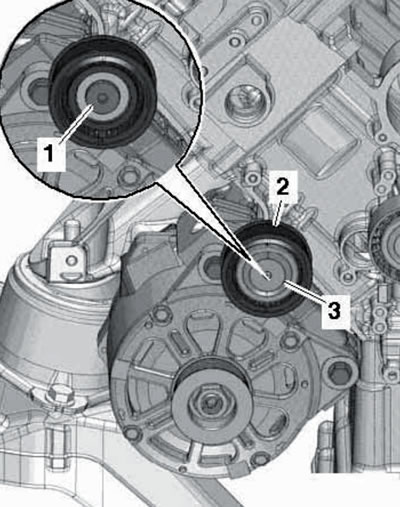
7. Disconnect the wiring from the generator (1 and 2 in Illustration 4.69 Chapter 2) and take her aside.
8. Unscrew the bolts and remove the generator (see illustration 4.70 Chapter 2). If the alternator is stuck in the bracket, screw the bolts back in at least 2 turns and tap them lightly to release the alternator mount threaded bushings.
9. Installation is carried out in reverse order. Use new self-locking fasteners. Tightening torques are specified in the Specifications.
3.0L 1st Generation Models, Water-Cooled Generator
10. Follow the steps described in paragraphs 1-3.
11. Remove the air cleaner (see Chapter 4).
12. Disconnect the air hoses (1-3 in illustration 15.11 Chapter 2).
13. Remove the bolts (2 and 3 in Illustration 5.26 of Chapter 2).
14. Remove the lid (3 in the illustration), unscrew the bolt (1) and remove the intermediate roller (2).
13.14. Removing the intermediate roller.
15. Remove the bolts (arrows in illustration 15.33 Chapter 2) generator (1).
16. Remove the right front wheel, sound insulation panels under the engine compartment (see Section 19 of Chapter 1) and the right front wheel arch liner (see Chapter 10).
17. Unscrew the bolt (see illustration 4.45 Chapter 2) and move the fuel cooling pump "V166" to the side without disconnecting the coolant hoses and electrical wiring. Remove the generator from the bracket. If the alternator is stuck in the bracket, screw the bolts back in at least 2 turns and tap them lightly to release the alternator mount threaded bushings.
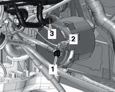
18. Clamp the coolant hoses (3 and 4 in the illustration) clamps No. 3094, disconnect the connector (1), disconnect the 30/V+ wire (2) from the generator and remove the generator towards the right wheel arch.
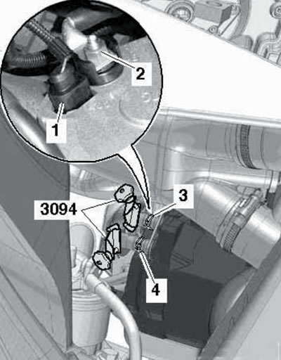
13.18. Removing a water-cooled generator.
19. Installation is carried out in reverse order. Tightening forces are specified in the Specifications.
2nd generation 3.0L models (air-cooled generator)
20. Disconnect the negative battery cable (see Section 10).
21. Loosen the drive belt, remove it and lock the tensioner (see Chapter 2).
22. Unscrew the generator mounting bolts (see illustration 4.70 Chapter 2). If the alternator is stuck in the bracket, screw the bolts back in at least 2 turns and tap them lightly to release the alternator mount threaded bushings.
23. Remove the right front wheel and the front sound insulation panel under the engine compartment (see Section 19 of Chapter 1).
24. Disconnect the air hose from the intercooler (right side).
25. Remove the bolts (2 and 3 in illustration 26.11 Chapter 2) and disconnect the air tube from the hoses (1 and 4).
26. Disconnect the connector (3 in illustration 26.10 Chapter 2), unscrew the bolts (1 and 4) and put aside the bracket together with the engine mount valve "N398", the vacuum receiver and the connected vacuum hoses.
27. Disconnect the wiring from the generator (1 and 2 in Illustration 4.69 Chapter 2).
28. Remove the generator (1 in the illustration) to the right from the opening between the side member (2) and the anti-roll bar (3).
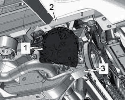
13.28. Removing the generator.
29. Installation is carried out in reverse order. To make installation of the generator easier, press the bushings of the mounting bolts slightly. Tightening forces are specified in the Specifications.
4.2L models
30. Disconnect the negative battery cable (see Section 10).
31. Remove the drive belt from the alternator pulley, and on models prior to 05.2009, additionally remove the belt tension roller (see chapter 2).
32. Disconnect the connector (5 in illustration 35.49 Chapter 2) and disconnect the air tubes (3 and 4).
33. Remove the bolts (see illustration) and remove the generator.
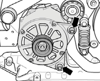
13.33. Generator fastening.
If the alternator is stuck in the bracket, screw the bolts back in at least 2 turns and tap them lightly to release the alternator mount threaded bushings.
34. Disconnect the wire from the generator (1 in the illustration), disconnect the connector (2) and disconnect the coolant hoses (3), having first pinched them.
13.34. Generator connections.
35. Installation is carried out in reverse order. Tightening forces are specified in Specifications.
The original publication in its entirety is posted on the website: AUDIMANUAL