
Table of contents: Six-cylinder petrol engines ↓ Six-cylinder diesel engines ↓ Eight-cylinder petrol engines (3.7… ↓
Cars are equipped with alternating current generators. Depending on the model and electrical equipment installed on the car, generators of different power can be installed. When installing additional electrical equipment, check that the generator power is sufficient to supply the new consumer.
The generator is driven by a poly-V belt from the engine crankshaft.
The generator is a three-phase synchronous electric machine with electromagnetic excitation. To convert alternating current into direct current, a rectifier on diodes is built into the generator. The voltage is regulated by a built-in microelectronic voltage regulator.
When the generator is running, the electric current flowing through the excitation winding creates a magnetic field around the rotor poles. When the rotor rotates, the rotor poles alternately pass under the stator coils, the magnetic flux changes in magnitude and direction and creates an electromotive force in the stator winding.
At high generator rotor speed, when the generator voltage becomes higher than 13.6–14.6 V, the voltage regulator locks and the current does not pass through the excitation winding. The generator voltage drops, the regulator unlocks and again passes the current through the excitation winding. The higher the generator rotor speed, the longer the regulator locks, and therefore the more the generator output voltage decreases. The regulator locks and unlocks at high frequency, so the voltage fluctuations at the generator output are not noticeable, and it can practically be considered constant, maintained at 13.6–14.6 V.
When checking the generator, as well as when operating the vehicle, it is necessary to follow a number of simple rules in order not to damage the generator:
- do not allow the generator to operate with the battery disconnected. When the generator operates with the battery disconnected, the voltage in the vehicle's on-board network increases when any power consumers are disconnected, which leads to failure of the vehicle's electronic equipment, including the voltage regulator and the generator rectifier unit;
- do not check the generator's performance for a "spark" even by briefly connecting the "positive" terminal of the generator to the "ground". In this case, a high current flows through the rectifier unit and the diodes are damaged. The generator voltage can only be checked with a voltmeter;
- the negative terminal of the battery should always be connected to the vehicle's ground, and the positive terminal to the generator terminal. Incorrect (reverse) connection of the battery will cause a sharp increase in the current passing through the generator diodes, and they will fail;
- do not check diodes with a voltage higher than 12 V or with a megohmmeter, as it has too high a voltage for diodes. In this case, the diodes will be broken during testing (a short circuit will occur). When checking the insulation of electrical wiring with a megohmmeter, disconnect all wires from the generator;
- it is necessary to disconnect all wires from the generator and battery when electric welding body components and parts;
- check electrical circuits and components and troubleshoot with the engine off and the battery disconnected.
Before removing the generator, disconnect the battery, first finding out if you have a radio activation code.
Turn off the ignition and disconnect the ground wire from the battery.
After installing the generator, connect the ground wire to the battery.
Turn on radio and enter the code into it.
Raise the power windows all the way up. Then press all power window switches again for at least 1 second to the closed position to activate the power window control unit.
Set the time on the clock.
Six-cylinder petrol engines
Removal
Release the clips and remove the lower engine compartment splash shield.
Disconnect and remove the generator air duct.
Unscrew the nuts and disconnect the wires from the terminals "30/B +" and "D +" of the generator (Fig. 18–12).
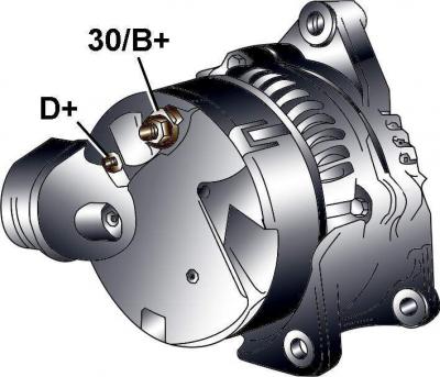
Fig. 18–12. Alternator terminal locations on six-cylinder gasoline engines

Fig. 18–13. Front air duct locations
Remove the front air ducts (Fig. 18–13).
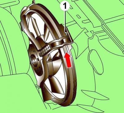
Fig. 18–14. Location of the casing retainer (1) and direction of rotation for removing the electric radiator fan
To remove the electric radiator fan, disconnect the electrical connector from the fan, remove the shroud retainer, turn the shroud in the direction of the arrow (Fig. 18–14), and remove the fan.
Loosen the screws and remove the poly V-belt cover.
Use chalk, marker or paint to mark the direction of rotation of the poly V-belt. If the poly V-belt rotates in the opposite direction during installation, it will be damaged.
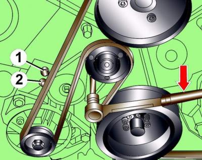
Fig. 18–15. Releasing the tension of the poly V-belt: 1 and 2 are the locations of the pins for fixing the tensioning mechanism. The arrow shows the direction of rotation of the Allen key to reduce the tension of the poly V-belt.
Using a 10 mm Allen key, loosen the tension on the poly V-belt by turning the tensioning mechanism clockwise until the holes align (Fig. 18–15).
Fix the tensioning mechanism in this position by inserting a 5 mm diameter steel rod into the hole.
Remove the poly V-belt from the generator pulley.
Drain the coolant from the cooling system.
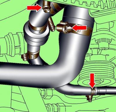
Fig. 18–16. Location of cooling system hose clamps
Loosen the clamps, disconnect the cooling system hoses and move them to the side (Fig. 18–16).
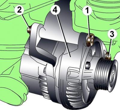
Fig. 18–17. Generator fastening elements on vehicles with six-cylinder petrol engines: 1 – nut, 45 N·m; 2 – bolt; 3 – bolt, 22 Nm; 4 – generator
Unscrew the generator upper mounting nut, holding the bolt from turning (Fig. 18–17). Remove the generator upper mounting bolt.
Unscrew the generator lower mounting bolt 3 and remove the generator.
Installation
Installation is carried out in the reverse order of removal, taking into account the following.
Check that the poly V-belt is positioned correctly on the pulleys.
Tighten the lower generator mounting bolt to 22 N·m.
Tighten the generator mounting nut to 45 Nm.
Tighten the nuts securing the wires to terminal "30/B+" with a torque of 16 N·m, to terminal "D+" with a torque of 4 N·m.
Six-cylinder diesel engines
Removal
Loosen the screws and remove the lower engine compartment splash guard.
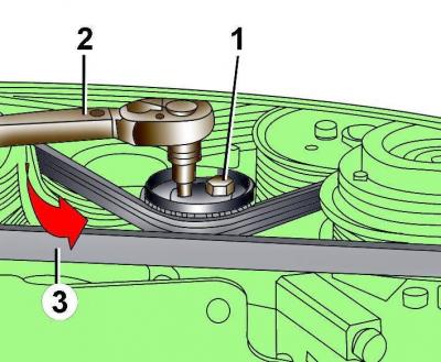
Fig. 18–18. Tensioning the air conditioning compressor poly V-belt: 1 – poly V-belt tension roller mounting bolt; 2 – air conditioning compressor poly V-belt; 3 – torque wrench
Loosen the bolt securing the tension roller of the air conditioner compressor poly V-belt and remove the belt from the pulleys (Fig. 18–18).
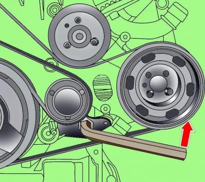
Fig. 18–19. Releasing the tension of the main poly V-belt
Using a socket wrench, turn the tensioning mechanism of the main poly V-belt counterclockwise, which will loosen the tension, fix the tensioning mechanism in this position with a pin (Fig. 18–19) with a diameter of 4 mm and remove the belt from the generator.
Before removing, mark the direction of rotation of the poly V-belt with chalk, marker or paint. If the previously used poly V-belt rotates in the opposite direction during installation, it will cause its destruction. Make sure the poly V-belt is correctly positioned on the pulleys.
Unscrew the nuts and disconnect the wires from the terminals "30/B +" and "D +" of the generator (see Fig. 18–12).
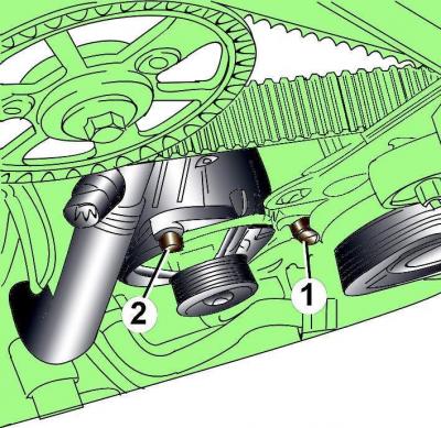
Fig. 18–20. Location of generator mounting bolts (1 and 2) on vehicles with six-cylinder diesel engines
Unscrew the generator mounting bolts and remove the generator from the vehicle (Fig. 18–20).
Installation
Installation is carried out in the reverse order of removal, taking into account the following.
Check that the poly V-belt is positioned correctly on the pulleys.
Tighten the right bolt 1 (see Fig. 18–20) of the generator mount to a torque of 22 N·m and the left bolt 2 to a torque of 45 N·m.
Eight-cylinder petrol engines (3.7 and 4.2 l)
Removal
Loosen the screws and remove the lower engine compartment splash guard.
Disconnect and remove the generator air duct.
Unscrew the nuts and disconnect the wires from the terminals "30/B +" and "D +" of the generator (see Fig. 18–12).
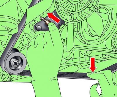
Fig. 18–21. Installing the 3204 tool for loosening the poly V-belt tension on eight-cylinder petrol engines
Loosen the tension of the poly V-belt using tools 3204 and remove the belt from the generator (Fig. 18–21).
Use chalk, marker or paint to mark the direction of rotation of the poly V-belt. If the poly V-belt rotates in the opposite direction during installation, it will be damaged.
Unscrew the generator upper mounting nut, holding the bolt from turning (see Fig. 18–17). Remove the generator upper mounting bolt.
Unscrew bolt 3 (see Fig. 18–17) of the lower generator mount and remove the generator.
Installation
Installation is carried out in the reverse order of removal, taking into account the following.
Check that the poly V-belt is positioned correctly on the pulleys.
Tighten the lower generator mounting bolt to 22 N·m.
Tighten the generator mounting nut to 45 Nm.
Tighten the nuts securing the wires to the "30/B+" terminal to a torque of 16 N·m, and to the "D+" terminal to a torque of 4 N·m.
[The original article is available on the online resource: AudiManual.ru]