
Table of contents: Six-cylinder petrol engines ↓ Six-cylinder diesel engines ↓ Eight-cylinder petrol engines (3.7… ↓ Checking and removing the starter… ↓
Six-cylinder petrol engines
Removal
Take it off generator.
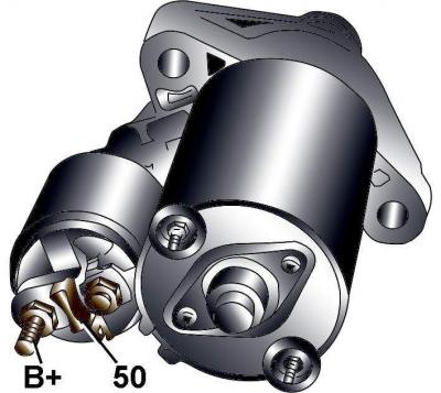
Fig. 18–22. Location of starter terminals on six-cylinder gasoline engines
Unscrew the nut and remove the wire from the "B +" terminals of the starter traction relay (Fig. 18–22).
Disconnect the electrical connector from the "50" terminals of the starter solenoid relay.
Unscrew the starter mounting bolts and remove the starter from the bottom of the vehicle. The lower bolt of the starter attachment also attaches the connection wire to the "ground" (engine/gearbox).
Installation
Installation is carried out in the reverse order of removal, taking into account the following.
Tighten the starter mounting bolts to 65 N·m.
Tighten the nut securing the wire to the "B +" terminal of the starter solenoid relay to a torque of 16 N·m.
Six-cylinder diesel engines
Removal
Take it off generator.
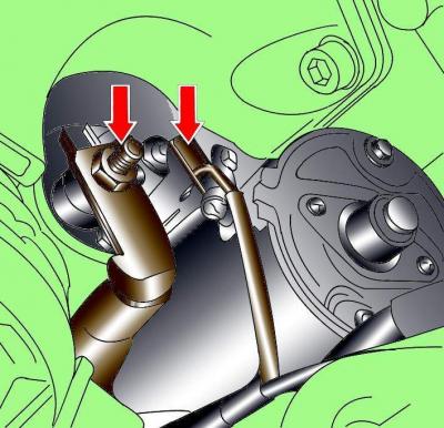
Fig. 18–23. Starter terminal locations on six-cylinder diesel engines
Unscrew the nut and remove the wire from the "B +" terminal of the starter solenoid relay (Fig. 18–23).
Disconnect the electrical connector from terminal "50" of the starter solenoid relay (see Fig. 18–23).

Fig. 18–24. Location of starter mounting bolts on six-cylinder diesel engines
Unscrew the upper bolt and nut securing the starter to the gearbox (Fig. 18–24).
Unscrew the lower bolt of the starter attachment and remove the starter (see Figure 18-24). The lower bolt of the starter attachment also secures the connection wire to the "ground" (engine/gearbox).
Installation
Installation is carried out in the reverse order of removal, taking into account the following.
Tighten the starter mounting bolts to 65 N·m.
Tighten the nut securing the wire to the "B +" terminal of the starter solenoid relay to a torque of 16 N·m.
Eight-cylinder petrol engines (3.7 and 4.2 l)
Removal
Take it off generator.
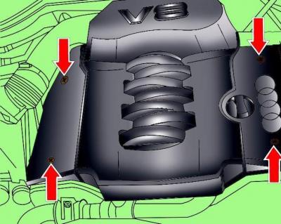
Fig. 18–25. Location of engine casing mounting screws
Loosen the screws and remove the engine casing (Fig. 18–25).
Loosen the clamps and remove the air intake pipe connecting the air filter and the throttle body.
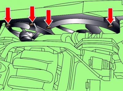
Fig. 18–26. Radiator Fan Shroud Bolt Locations
Unscrew the bolts, remove the radiator fan shroud and move it to the side without disconnecting the wires from it (Fig. 18–26).
Remove the cover from the suspension strut and air filter housing.
Install VAG 3180 holders onto the engine.
Check that all electrical wires, hoses, pipes and lines are disconnected from the engine.
Hang the clamp on a hoist with a lifting capacity of at least 500 kg and secure it to the holders on the engine.
Install a 10–222A/4 adapter and a 10–222A lifting device to the front suspension strut supports to support the engine.
Attach the 3033 lifting device to the engine and secure it to the engine.
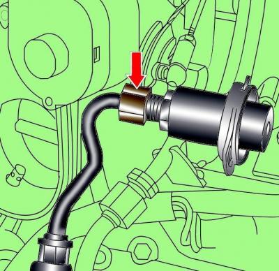
Fig. 18–27. Location of the connecting nut for fastening the fuel line to the pressure regulator
Unscrew the union nut and disconnect the fuel line from the pressure regulator (Fig. 18–27).
Insert the additional hook of the 10-222A lifting device into the eye on the pressure regulator.
Rotate the screw of the 10–222A lifting device and lift the engine with the 3033 grip and additional hook until the weight of the engine and gearbox is supported by the lifting device.
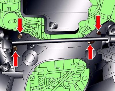
Fig. 18–28. Location of engine mounting bolts to the lower frame
Unscrew the lower bolts (Fig. 18–28) securing the engine to the lower frame.
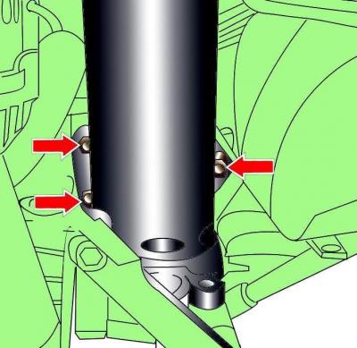
Fig. 18–29. Location of torque compensator support mounting bolts
Unscrew the bolts securing the right support of the torque compensator (Fig. 18–29).
Rotate the 10-222A lifting device screw to raise the engine until the engine mounts are clear of the lower frame.
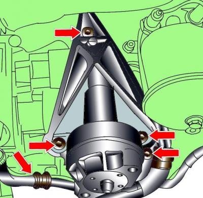
Fig. 18–30. Location of right engine mount mounting bolts and wire clamps
Unscrew the bolts securing the right engine support and release the wire clamps (Fig. 18–30).
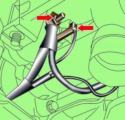
Fig. 18–31. Starter terminal locations on eight-cylinder gasoline engines
Unscrew the nut and remove the wire from the "B +" terminal of the starter solenoid relay (Fig. 18–31).
Disconnect the electrical connector from terminal "50" of the starter solenoid relay (see Fig. 18–31).
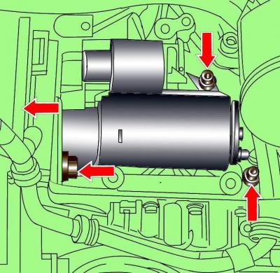
Fig. 18–32. Location of starter mounting bolts
Unscrew the lower bolt securing the starter to the engine (Fig. 18–32).
Unscrew the upper bolt securing the starter to the gearbox.
Unscrew the two bolts and remove the starter.
Installation
Installation is carried out in the reverse order of removal, taking into account the following.
Tighten the starter mounting bolts to 65 N·m.
Tighten the nut securing the wire to the "B +" terminal of the starter solenoid relay to a torque of 16 N·m.
Checking and removing the starter traction relay
Remove the starter.
Using additional large-section wires, connect the starter housing to the negative terminal of the battery, and the positive terminal to the "50" terminal. If the starter drive pinion moves forward, but the starter motor does not rotate, then the starter anchor is faulty or the traction relay contacts are burnt.
If the starter gear does not move forward, then the traction relay is faulty and must be replaced.
Unscrew the nut and disconnect the wire going from the starter motor to the lower contact of the traction relay.
Unscrew the screws and remove the solenoid relay from the starter.
The original article is available on the website audimanual