
When the starter is turned on, current from the battery begins to flow through the winding of the starter traction relay. The relay armature is pulled in and the relay contacts are closed. At the same time, the relay armature moves the overrunning clutch with the gear through the lever. The hub of the overrunning clutch also turns the gear on the helical splines of the starter armature shaft, which facilitates its engagement with the flywheel ring gear. Current flows through the closed contacts of the traction relay, feeding the stator and armature windings, and the starter armature begins to rotate together with the hub and overrunning clutch.
After the engine is started, the rotation speed of the pinion exceeds the rotation speed of the starter anchor. In this case, the overrunning clutch rotates freely, and the torque is not transmitted from the engine flywheel to the starter anchor shaft. After releasing the ignition key, the power supply circuit of the traction relay windings through the ignition switch is opened, the anchor of the traction relay is pressed back to its original position by the spring, the relay contacts are opened and the drive pinion disengages from the flywheel ring gear.
If the starter does not work in the "engine start" key position, the following reasons are possible:
- the battery is faulty;
- open circuit between the ignition switch, traction relay, battery and starter;
- traction relay is faulty;
- mechanical or electrical defect of the starter.
To check the battery, turn on the headlights. If they dim after a few seconds, the battery is discharged. Recharge or replace the battery. If the headlights do not dim, turn on the starter and watch the light. If they dim, then voltage is reaching the starter and the fault is in it. If the headlights continue to burn brightly (and there is no click of the starter traction relay), this indicates that there is damage in the electrical circuit or the traction relay is faulty. If the starter turns slowly and the battery is in good condition, this indicates that the starter is faulty or there is significant resistance in the starter electrical circuit.
If damage to the electrical circuit is suspected, disconnect the battery and clean all connections and contacts in the starter supply circuit. Reconnect the battery and, using a voltmeter, check the voltage across the electrical circuit elements to the starter.
If the battery and electrical circuit are in good condition, remove the power wire from the traction relay and connect a voltmeter to it. Turn the ignition key to the "engine start" position. In this position, there should be full battery voltage.
The contacts of the traction relay can be checked by connecting a voltmeter between the contact of the traction relay connected to the starter and the ground. When turning the ignition key to the "engine start" position, the voltmeter should show voltage. If there is no voltage, the solenoid of the traction relay is faulty or the contacts of the traction relay are burnt.
If the electrical circuit and traction relay are in good condition, then the starter is faulty.
Removal
Remove the ground cable from the battery.
Attention
- When the battery terminals are disconnected, the memory units of the control units erase the data on the recorded faults, so before disconnecting the battery terminals, it is advisable to contact a specialized workshop to recall the faults recorded in the memory. After connecting the battery terminal, it is necessary to activate and reprogram the electric windows, as well as the position of the rear-view mirrors and seats.
- Also, if the car has a radio receiver with a code, before disconnecting the terminals from the battery, check that you have the code to reactivate the receiver. Otherwise, the radio receiver can only be put into operation at a specialized station.
Place the vehicle over an inspection pit or lift it on a lift.
V6 engines
Before removing the starter, remove the generator.
Petrol engine 1.8-I/diesel engine 1.9-I-TDI
Remove the lower engine compartment splash shield.
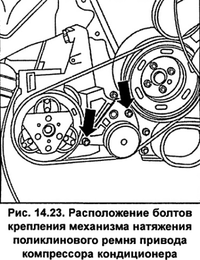
Unscrew the bolts and remove the tensioner mechanism of the poly V-belt of the air conditioning compressor drive (see fig. 14.23).
Remove the poly V-belt.
Unscrew the air conditioning compressor and, without disconnecting the pipes from it, move it to the side.
All engines
Unscrew the nut and disconnect the wire from terminal B+ 2 (fig. 14.24) starter.
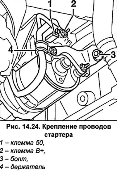
Disconnect the electrical connector from terminal 50 of the traction relay.
Unscrew bolt 3 (fig. 14.24) fastening the starter rear support bracket to the engine cylinder block.
Unscrew and remove the starter wire holder 4 (fig. 14.24).
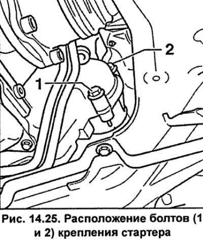
Unscrew bolts 1 and 2 (fig. 14.25) starter mounts.
Cars with automatic transmission
Remove the right front wheel. Unscrew bolt 1 from under the wheel arch (fig. 14.26).
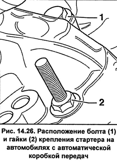
From the engine compartment side, unscrew nut 2 (fig. 14.26).
Remove the starter by moving it downwards.
Installation
Install the starter from below and secure it with bolt 2 (fig. 14.25), tightening it to a torque of 65 Nm.
Install and screw the starter wire holder 4 (fig. 14.24).
Screw bolt 3 (fig. 14.24) fastening the starter rear support bracket to the engine cylinder block.
Connect the electrical connector to terminal 50 of the traction relay.
Screw the wire to the B+ terminal of the traction relay and tighten the nut to a torque of 16 Nm.
V6 Engine
Install the alternator. Install the poly V-belt and adjust its tension. Lower the car.
Connect the ground wire to the battery.
If your vehicle has a radio with a code, reprogram it.
Set the clock. Activate the electric windows.
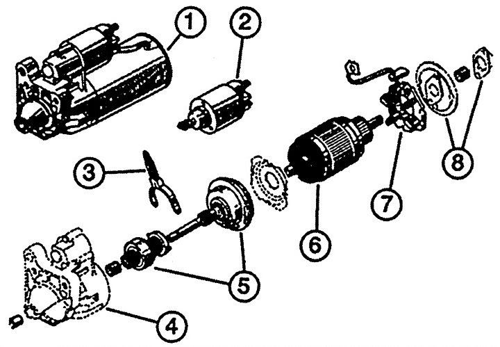
Fig. 14.22. Starter
1 - starter,
2 - traction relay,
3 - drive lever,
4 - drive side cover,
5 - overrunning clutch,
6 - anchor,
7 - brush holder,
8 - back cover with bearing.