
The generator is driven by a belt from the engine crankshaft.
The generator is a three-phase synchronous electric machine with electromagnetic excitation. To convert alternating current into direct current, a rectifier on diodes is built into the generator. The voltage is regulated by a built-in microelectronic voltage regulator.
When the generator is operating, the electric current flowing through the excitation winding creates a magnetic flux around the rotor poles. When the rotor rotates, either the south or north pole of the rotor passes under each stator tooth, and the working magnetic flux passing through the stator teeth changes in magnitude and voltage. This variable magnetic flux creates an electromotive force in the stator winding. The wedge-shaped rotor pole pieces are selected in such a way that it allows the electromotive force curve to be close to sinusoidal.
At high generator rotor speed, when the generator voltage becomes higher than 13.6-14.6 V, the voltage regulator is locked and the current does not pass through the excitation winding. The generator voltage drops, the regulator is unlocked and again passes the current through the excitation winding. The higher the generator rotor speed, the longer the regulator is locked, and therefore the more the voltage at the generator output decreases. The process of locking and unlocking the regulator occurs with a high frequency, so the voltage fluctuations at the generator output are not noticeable, and it can practically be considered constant, maintained at a level of 13.6-14.6 V.
When checking the generator, as well as when operating the vehicle, it is necessary to follow a number of simple rules in order not to damage the generator:
- do not allow the generator to operate with the battery disconnected from the generator terminal. Without a battery, dangerous overvoltage pulses occur in the vehicle's on-board network when any electrical consumers are disconnected. These overvoltage pulses can damage the vehicle's electronic equipment, including the voltage regulator and the generator's rectifier block diodes;
- do not check the generator's performance for a spark, even by briefly connecting the positive clamp of the generator to ground. In this case, a significant current flows through the diodes, and they are damaged. The generator voltage can only be monitored with a voltmeter;
- the negative terminal of the battery must always be connected to the vehicle's ground, and the positive terminal must be connected to the alternator terminal. Incorrect (reverse) connection of the battery will immediately cause increased current to flow through the alternator diodes, causing them to fail;
- do not check diodes with a voltage higher than 12 V or with a megohmmeter, as it has too high a voltage for diodes and they will be broken during testing (a short circuit will occur). When checking the insulation of electrical wiring with a megohmmeter, it is necessary to disconnect all wires from the generator;
- it is necessary to disconnect all wires from the generator and from the battery when electric welding any body parts;
- it is necessary to check the circuits and components of electrical equipment and troubleshoot problems with the engine not running and the battery disconnected.
- before removing the wires from the generator, it is necessary to mark them so that they can be reinstalled strictly in their proper places.
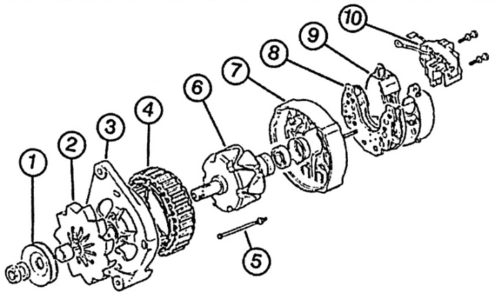
Fig. 14.10. Generator
1 - V-belt pulley,
2 - fan impeller,
3 - cover,
4 - winding,
5 - screw,
6 - rotor,
7 - back cover,
8 - rectifier block,
9 - plastic cover,
10 - voltage regulator.