
Connect a voltmeter to the battery terminals.
While monitoring the voltmeter readings, start the engine. In starter mode, the voltage may drop to 8 V (at an outside temperature of 20°C).
Increase the engine speed to 3000 rpm, and the voltage should increase to 13.7-14.6 V. This indicates that the generator and voltage regulator are working properly.
At an engine speed of 3000 rpm, turn on the high beam headlights or other powerful power consumers, while the voltage drop should be no more than 0.4 V.
In case of significant voltage deviations during testing, the generator must be checked in a specialized workshop.
Gasoline engine
Removal
The removal and installation of a 1.8-1 petrol engine generator with air conditioning is shown.
Remove the ground cable from the battery.
Attention
- When the battery terminals are disconnected, the memory units of the control units erase the data on the recorded faults, so before disconnecting the battery terminals, it is advisable to contact a specialized workshop to recall the faults recorded in the memory. After connecting the battery terminal, it is necessary to activate and reprogram the electric windows, as well as the position of the rear-view mirrors and seats.
- Also, if the car has a radio receiver with a code, before disconnecting the terminals from the battery, check that you have the code to reactivate the receiver. Otherwise, the radio receiver can only be put into operation at a specialized station.
Unscrew, remove from the bracket and move to the side the expansion tank together with the hoses connected to it.
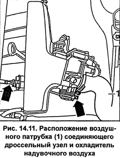
Remove the air duct 1 (fig. 14.11) connecting the throttle assembly and the charge air cooler.
Remove the poly V-belt.
Remove the poly V-belt tensioner mechanism.
Release the two clamps 2 (fig. 14.12) and remove holder 1.
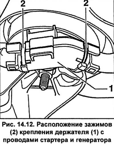
Remove from holder 1 (fig. 14.12) wires from the starter and generator.
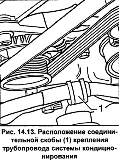
Unscrew the connecting bracket 1 (fig. 14.13) air conditioning system pipeline fastenings located on top of the torque compensation support.
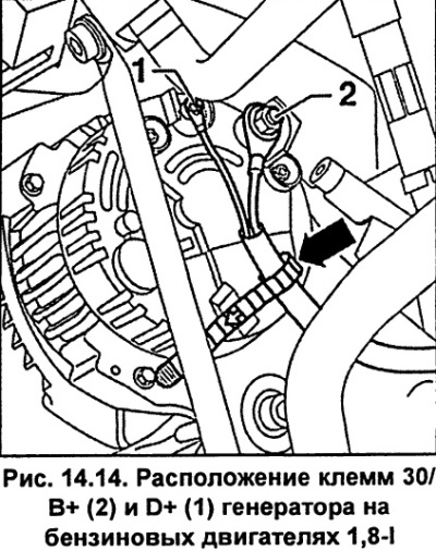
Unscrew the nuts and disconnect the wires from the terminals "30/V +" and "D +" of the generator (fig. 14.14).
Unscrew nut 2 (fig. 14.15) upper generator mount, holding bolt 1 from turning. Remove the upper generator mount bolt.
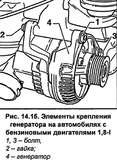
Unscrew the generator lower mounting bolt 3 (fig. 14.15) and remove the generator. When removing the generator, be careful not to damage the air conditioning system piping.
Installation
Installation is carried out in the reverse order of removal, taking into account the following points.
Check that the poly V-belt is positioned correctly on the pulleys.
Tighten the lower generator mounting bolt to 45 Nm.
Tighten the generator mounting nut to 22 Nm.
Tighten the nuts securing the wires to the "30/B+" terminal with a torque of 16 Nm, and to the "D+" terminal with a torque of 4 Nm.
If your vehicle has a radio with a code, reprogram it.
Set the time on the clock.
Activate the power windows.
Differences in 2.4-/2.8-I engines
Remove the poly V-belt.
Disconnect the air duct 3 (fig. 14.16) from the back of the generator.
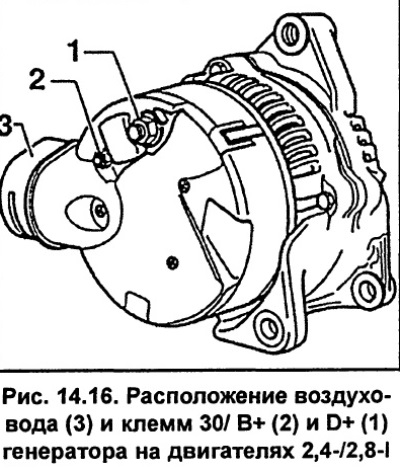
Unscrew the nuts and disconnect the wires from the terminals "30/V +" and "D +" of the generator (fig. 14.16).
TDI engine
Removal
Remove the ground cable from the battery.
Caution. When disconnecting the battery terminals, the memory units of the control units erase the data on the recorded faults, so before disconnecting the battery terminals, it is advisable to contact a specialized workshop to recall the faults recorded in the memory. After connecting the battery terminal, it is necessary to activate and reprogram the electric windows, as well as the position of the rear-view mirrors and seats.
Also, if the car has a radio receiver with a code, before disconnecting the terminals from the battery, check that you have the code to reactivate the receiver. Otherwise, the radio receiver can only be put into operation at a specialized station.
Remove the poly V-belt.
Unscrew the nuts and disconnect the wires from the terminals "30/V +" and "D +" of the generator (fig. 14.17).
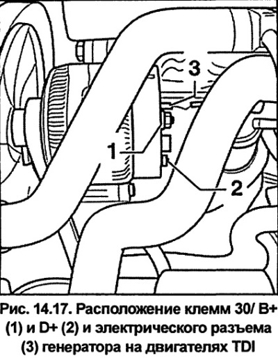
Disconnect electrical connector 3 from the generator (fig. 14.17).
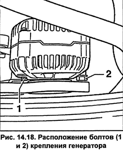
Unscrew bolts 1 and 2 (fig. 14.18) and remove the generator. When removing the generator, push the cooling system hose aside and remove the generator upwards.
AFB Engine. Disconnect the connector from the hydraulic engine mount and remove the alternator downwards. When removing the alternator, be careful not to damage the air conditioning system line.
Installation
Installation is carried out in the reverse order of removal, taking into account the following points.
AFB Engine
Connect the connector to the hydraulic engine mount.
Tighten bolt 1 (fig. 14.18) torque of 45 Nm.
Tighten bolt 2 (fig. 14.18) torque of 20 Nm.
Tighten the nuts securing the wires to the "30/B+" terminal with a torque of 16 Nm, to the "D+" terminal - with a torque of 4 Nm (see fig. 14.17).
If your vehicle has a radio with a code, reprogram it.
Set the time on the clock.
Activate the power windows.
[This article was previously published on the resource AudiManual.ru]