
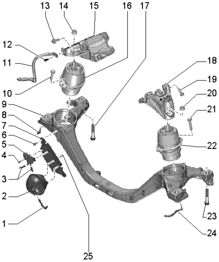
26.1. Engine support and crossmember installation details:
1, 3, 8, 24 - Vacuum hoses;
2 - Vacuum receiver;
4 - Bolt, 5 Nm;
5 - Solenoid valve "N398" of the electrohydraulic engine support;
6 - Bolt, 9 Nm;
7 - Receiver bracket (1) and valve (5);
9 - Engine crossmember;
10, 21 - Bolt, 60 Nm;
11 - Ground wire;
12 - Bolt, 15 Nm;
13, 19 - Bolt, 50 Nm, then tighten to an angle of 90°;
14, 20 - Nut, 75 Nm;
15 - Support bracket 16;
16 - Right engine mount;
17, 23 - Bolt, subject to replacement, 120 Nm, then tighten to an angle of 180°;
18 - Support bracket 22;
22 - Left engine mount;
25 - Bolt, 2.5 Nm.
2. Loosen the clamps (see illustration 4.16) and remove the air hose.
3. Remove both sound insulation panels under the engine compartment (see Section 19 of Chapter 1).
4. Remove the anti-roll bar (see Chapter 9).
5. Give the nut (1 in the illustration) and unscrew the bolts (arrows) securing the support on both sides.
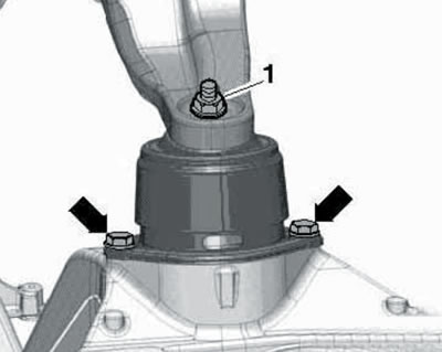
26.5. Engine support fasteners.
6. Remove the wheel arch liners from both front wheel arches (see Chapter 10).
7. Disconnect the ground wire from the right side member (see illustration 4.47).
8. Install beam No. 10 - 222A with supports N210 - 222A/22 and two spindles No. 3033 located at the rear onto the flanges of the front wings (see illustration).
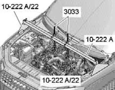
26.8. Hooking the devices onto the rear lifting eyes.
Hook both spindles into the rear lifting eyes of the engine.
9. Separate the vacuum hoses (see illustration) from both engine mounts and remove these hoses from the engine crossmember.
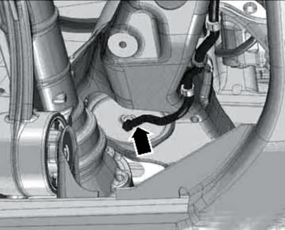
26.9. Vacuum hose on engine mount.
10. Disconnect the connector (3 in the illustration), disconnect the vacuum hose (2) and move it to the side.
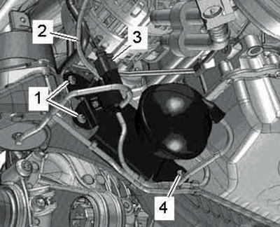
26.10. Removing the vacuum receiver bracket and valve "N398".
Unscrew the bolts (1 and 4) and remove the bracket together with the vacuum receiver and the solenoid valve "N398" of the engine mount.
11. Loosen the clamps (1 and 4 in the illustration) and separate the air hoses.
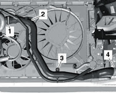
26.11. Fastening air hoses to the fan casing.
Remove the bolts (2 and 3) and remove the air tube downwards.
12. Unscrew the two bolts and remove the heat shield (And in illustration 4.43) steering mechanism. Set the front wheels in the straight ahead position and secure the steering wheel with tape to prevent it/steering column from changing position. Remove the hinge mounting bolt (B) and separate it from the steering gear.
13. Install the VAG1383A transmission jack under the power unit (see illustration 13.8).
14. Mark the installation position of the subframe and engine crossmember relative to the side members, and then unscrew the bolts (3 and 4 in illustration 4.51) and lower the front side of the subframe together with the engine crossmember.
15. Using spindles No. 3033, evenly raise the power unit by 40 mm (determined by the spindle threads), remove the engine mounts and crossmember.
16. Installation is carried out in reverse order.
(The original article is posted on the resource: AUDIMANUAL)