
Note: The engine is removed together with the AT and subframe from under the engine compartment (with the front panel installed), and then separated from the transmission.
Removal
1. Set the selector lever to "N" so that the propeller shaft can rotate freely. On models with air suspension, activate the vehicle jacking mode (see Introduction).
2. Disconnect the negative battery cable (see Chapter 5).
3. Drain the refrigerant from the refrigeration unit (see Chapter 3).
4. Pump out the power steering fluid from the reservoir and open the expansion tank of the cooling system (see Chapter 1).
5. Remove both front wheels (see Introduction), both soundproofing panels under the engine compartment (see Section 19 of Chapter 1) and fenders of both front wheel arches (see chapter 10).
6. Prepare to collect coolant leaking from under the engine.
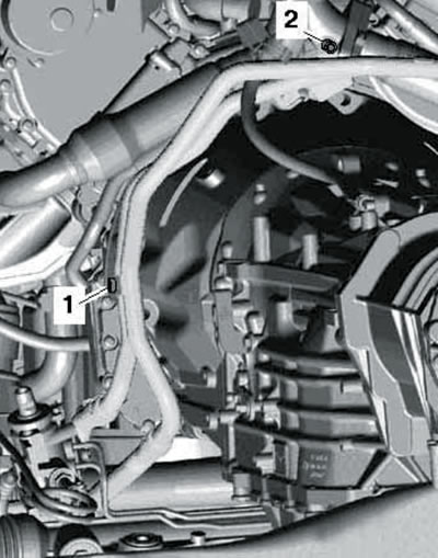
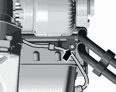
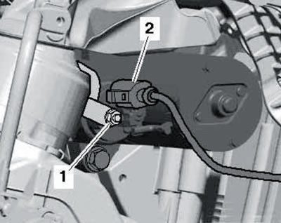
7. Disconnect the hose from the left coolant pipe (see illustration) and let the liquid drain.
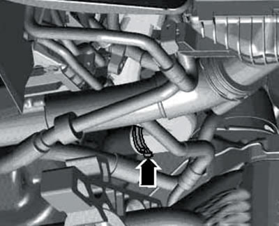
4.7. Connecting the hose to the left coolant pipe.
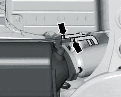
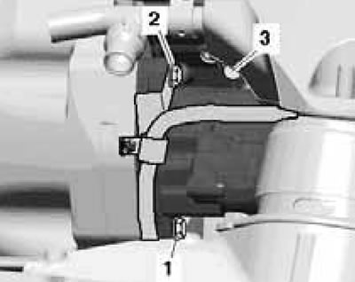
8. Disconnect the connector (2 in the illustration) coolant temperature sensor "G83" at the radiator outlet.
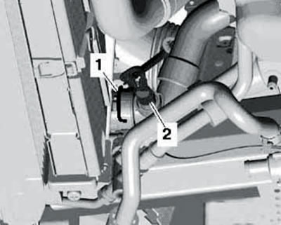
4.8. Connector of sensor G83 (2) and retainer (1) of the right lower hose on the radiator.
Disconnect the right lower coolant hose (1) from the radiator and allow the coolant to drain.
9. Disconnect the hoses from the coolant pipes of the heater radiator and let the liquid drain (see illustration).
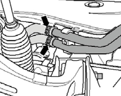
4.9. Connecting hoses to coolant pipes.
10. Disconnect the hose from the right coolant pipe (see illustration) and let the remaining liquid drain.
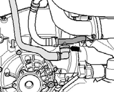
4.10. Connecting the hose to the right coolant pipe.
11. Remove the upper engine cover and the upper radiator shroud (see Section 19 of Chapter 1).
12. Disconnect the coolant hose (1 in the illustrations) and disconnect the vacuum hose (2) going to the vacuum receiver.
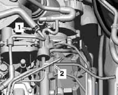
4.12a. Coolant hose (1) and vacuum hose (2) of BUG/BUN engines.
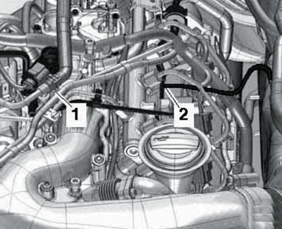
4.12b. Coolant hose (1) and vacuum hose (2) for CASA/CASB, CATA and CCMA engines.
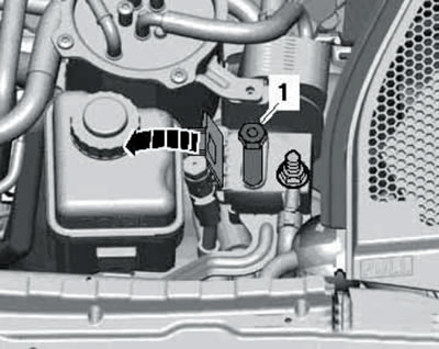
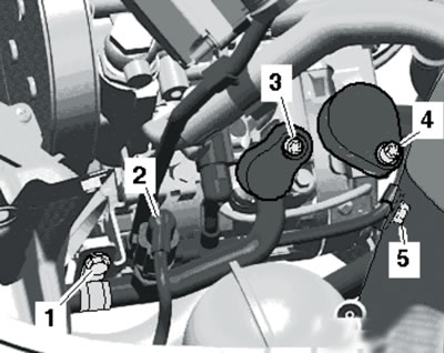
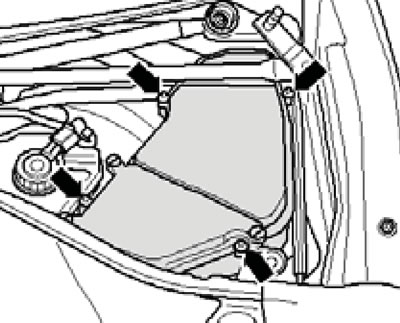
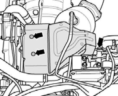
13. Remove the bolts (1 and 2 in the illustration), loosen the nut (4) and set the fuel filter aside without disconnecting the fuel hoses (3, 5 and 6) from it.
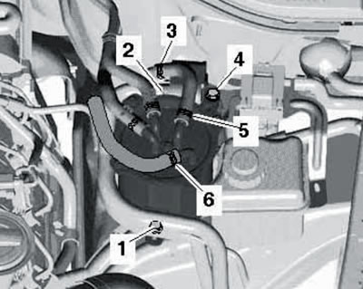
4.13. Fasteners (1, 2 and 4) and hoses (3, 5 and 6) of the fuel filter.
14. Remove the bolts (1...4 in the illustration) and move the fuel cooler to the side.
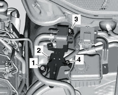
4.14. Fuel filter bracket fastener.
The fuel filter bracket remains in place.
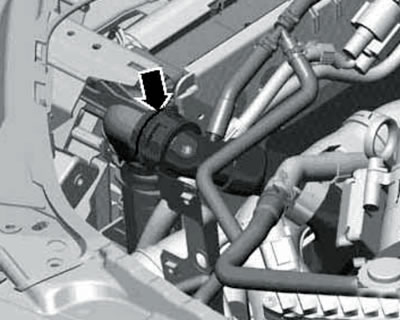
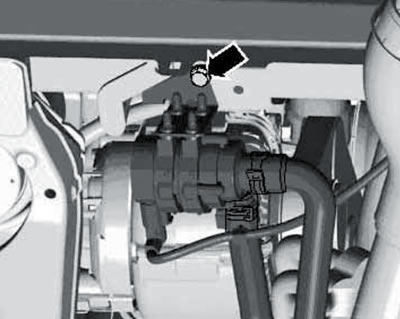
15. Open the lid (arrow in the illustration) terminals B+, disconnect the positive wire (1) going to the starter and generator, and move it to the side.
4.15. Positive battery terminal connection.
16. Remove the air hose (see illustration).
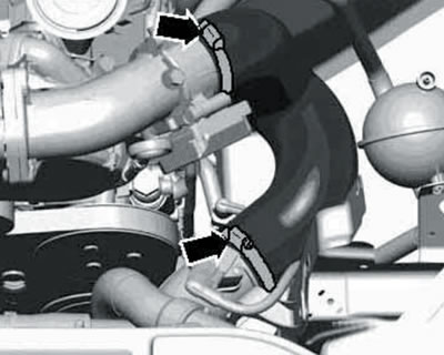
4.16. Air hose clamps.
17. Disconnect the connector (3 in the illustration), unscrew the bolts (1 and 2) and remove the throttle module from the intake manifold.
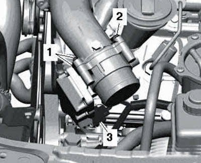
4.17. Connector (3) and bolts (1 and 2) of the throttle module.
18. Place a cloth under the power steering pump to collect any leaking fluid. Clamp the hose with clamp No. 3094 (see illustration), loosen the clamp (1) and disconnect the hose from the pump.
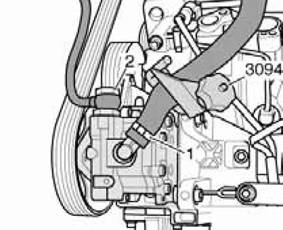
4.18. Power steering pump connections.
Cap the hose and pump to prevent dirt from getting into them.
Note: Do not remove the hollow bolt (2).
19. Disconnect the connector (2 in the illustration, if available), remove the holders (1 and 5) and disconnect the refrigerant lines (3 and 4) from the air conditioning system compressor.
4.19. Air conditioning system compressor connections.
Cap the refrigerant lines and the corresponding compressor ports to prevent dirt or moisture from entering the refrigerant circuit. Do not kink or stretch refrigerant lines.
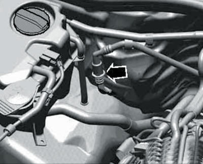
20. Disconnect the upper left coolant hose from the radiator (see illustration).
4.20. Upper left coolant hose on the radiator.
21. Disconnect the air hoses at the locations (2 and 3 in the illustration).
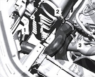
4.21. clamp (1) and clamps (2 and 3) of air hoses.
22. Remove the air tube (see illustration).
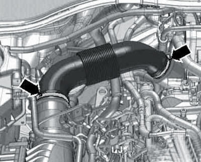
4.22. Air tube clamps.
23. Disconnect the front differential ventilation hose from the air cleaner cover (see illustration 16.10 Chapter 1).
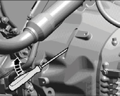
24. On models with air suspension, use a screwdriver to press the retaining ring (1 in the illustration) forward from the connection.
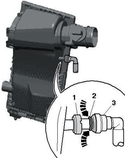
4.24. Separating the ventilation hose from the air cleaner housing.
Press the ring (2) in the direction of the arrows and remove the ventilation hose (3) from the air cleaner cover.
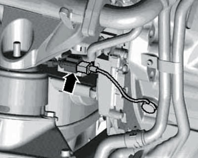
25. Remove the electrical wiring connector (see illustration) from the bracket and disconnect.
4.25. Electrical wiring connector.
Remove the connector bracket from the cylinder head cover.
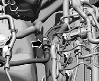
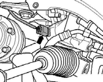
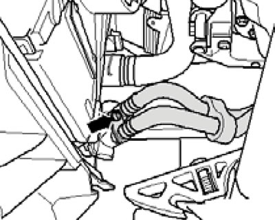
26. Disconnect the vacuum hose going to the brake booster (see illustration).
4.26. Vacuum hose connection.
27. Disconnect the feeder (1 in the illustration) and return (2) fuel lines from the air intake chamber dividing panel.
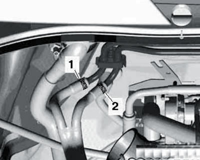
4.27. Supply (1) and return (2) fuel lines.
Note: Fuel may remain hot for some time after the engine is turned off. When disconnecting fuel lines, wrap the connection with a thick layer of cloth and slowly disconnect.
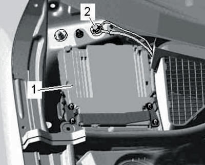
28. Remove the electrical wiring connectors from the bracket (1 and 2 in the illustration), separate them and move them aside.
29. Remove the air intake chamber cover (see Section 19 of Chapter 1) and the electronics compartment cover (see illustration).
4.29. Fastening the electronics compartment cover.
30. In the electronics compartment, disconnect the connectors (1-3 in the illustration) and move the wiring to the side.
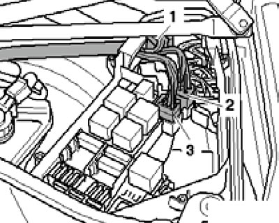
4.30. Electrical wiring connectors in the electronics compartment.
31. Disconnect the ground wire (2 in the illustration) and remove the ECM (1) as described in Chapter 5.
4.31. Ground wire (2) near ECM (1).
Move aside the wiring going to the engine.
32. Loosen the upper control arm nut a few turns and press out the joint using the T10187 puller (see illustration), and then finally loosen the lever nut.
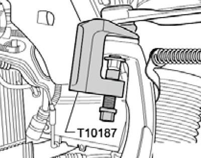
4.32. Separating the upper arm from the steering knuckle.
Separate the other upper control arm in the same way.
33. Disconnect the left and right ABS wheel sensor wiring connectors (see illustration).
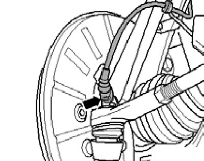
4.33. ABS wheel sensor connector.
34. Remove the bolts on both sides of the car (arrows in the illustration) wiring holder, then unscrew the bolts (1) securing the caliper and tie it with wire in the wheel arch.
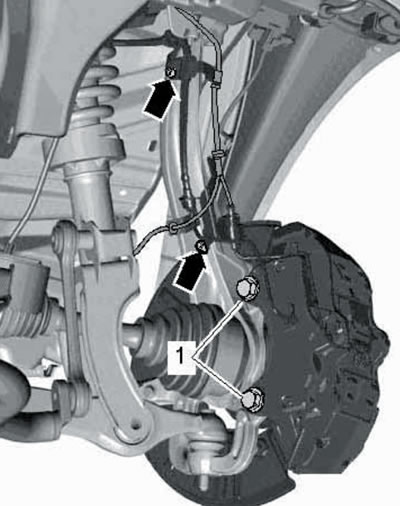
4.34. Bolts for fastening electrical wiring (arrows) and support (1).
Note: After removing the brake mechanism, do not press the brake pedal.
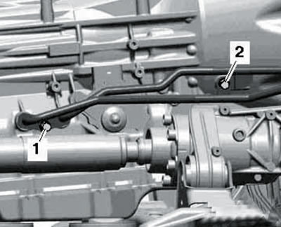
35. Loosen the lower bolt connections on both sides (2 in the illustration) on the stabilizer and loosen the nuts of the bolts (1) on the suspension struts.
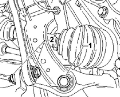
4.35. Stabilizer fastener (2) and suspension strut bolt (1).
The bolts themselves should be removed later.
36. Remove the rear propeller shaft mounting bolts on the transfer case (see illustration).
4.36. Bolts for fastening the rear propeller shaft to the transfer case.
Slide the rear propeller shaft assembly toward the rear final drive (CV joints can be moved in the axial direction). Tie up the end of the shaft.
37. Remove the soundproofing panel bracket (see illustration).
4.37. Soundproofing bracket fastening.
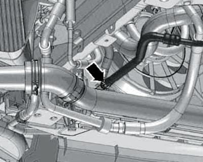
38. Separate the exhaust pipe on the clamp (see illustration), without allowing the flexible sections to bend more than 10°.
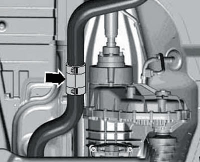
4.38. Exhaust pipe clamp.
39. Remove the exhaust pipe bracket from the side member (see illustration).
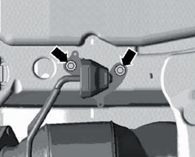
4.39. Fastening the exhaust pipe bracket to the side member.
40. Remove temperature sensor No. 1 ("G506") or No. 3 ("G495") in front of the particulate filter (see illustration).
4.40. Temperature sensor before the diesel particulate filter.
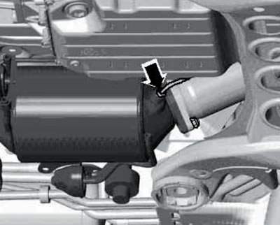
41. Disconnect the hoses (see illustration), going to sensor No. 1 "G450" exhaust gas temperature from the pressure pipes of the diesel particulate filter.
4.41. Hoses on the diesel particulate filter tubes.
42. Disconnect the steering gear wiring connector (see illustration).
4.42. Steering gear connector.
43. Remove the heat shield (And in the illustration) steering mechanism.
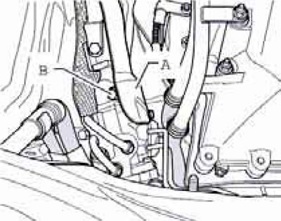
4.43. Heat shield (A) and hinge bolt (B).
Set the front wheels in the straight ahead position and secure the steering wheel with tape to prevent it/steering column from changing position. Remove the hinge mounting bolt (B) and separate it from the steering gear.
44. Prepare to collect the power steering fluid and on the left side of the dash, disconnect the power steering fluid line (see illustration), going to the power steering fluid radiator.
4.44. Power steering fluid line connection.
Plug any open lines to prevent dirt from getting into them.
45. Unscrew the bolt (see illustration) and move aside the fuel cooling pump "V166".
4.45. Fuel cooling pump bolt.
46. Unscrew the bolt (see illustration) and disconnect the ATF lines from the ATF temperature regulator.
4.46. ATF line mounting bolt on temperature regulator.
Seal any open holes to prevent dirt from getting in.
47. Unscrew the ground connection bolt on the right side member (see illustration).

4.47. Ground connection bolt.
48. Disconnect the AT wiring connectors (1...3 in the illustration).
4.48. Electrical wiring connectors AT "09D".
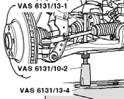
49. Install the required supports from the VAS6131/10, -/11, and -/13 kits onto the VAS6131 alignment table. Tighten the support fasteners on the table by hand, install the alignment table on a transmission jack, and position it horizontally under the powertrain. The supports from sets VAS6131/10 and -/11 must be positioned on the front side of the subframe as shown in the illustration.
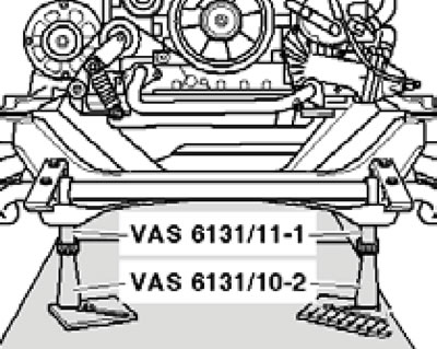
4.49. Supports under the front side of the subframe.
Make sure the threaded spindles are screwed in completely.
50. Install supports from sets VAS6131/10 and -/13 under the engine crossmember, suspension struts, rear side of the subframe and the AT holder (left and right), as shown in the illustrations.
4.50a. Supports under the engine crossmember.
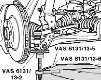
4.50b. Supports under the suspension struts.
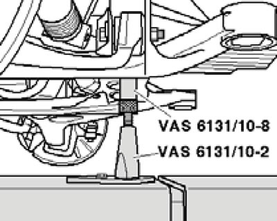
4.50 sec. Supports under the rear side of the subframe.
4.50d. Supports under the AT holder.
Drive the spindles of all the supports upwards so that their centering projections touch the support points. Tighten the support plates of the supports on the coordinate table with a torque of 20 Nm.
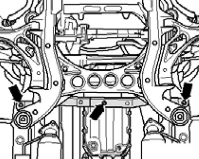
51. Mark the installation position of the subframe, engine crossmember and AT holder relative to the side members, and then unscrew the bolts in the sequence (1...4 in the illustration).
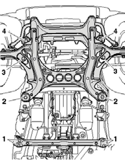
4.51. Fastening of the subframe, engine crossmember and AT holder.
Remove the bolts (1 in illustration 4.35) on both sides.
52. Make sure that all wiring lines and connectors between the engine, AT, subframe and body are disconnected. Carefully lower the power unit together with the subframe from under the car by 200 mm (see illustration), guiding so as not to damage any parts.
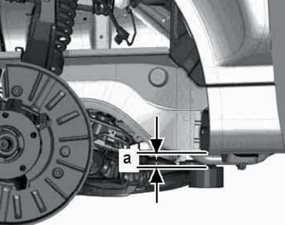
4.52. Distance for lowering the power unit.
Direct the suspension struts behind the side members.
53. Remove the bolts (1, 3 and 4 in the illustration) and slightly move the selector cable heat shield to the side.

4.53. Fastening the heat shield.
54. Press the hinge (2 in the illustration) selector cable from the selector mechanism lever using lever No. 80 - 200.
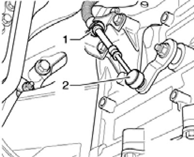
4.54. Disconnecting the cable from the AT.
Then pull out the lock (1) and remove the selector cable from the AT without bending it. Lower the power unit completely.
Separation of the engine from the AT
55. Secure the VAS6131/13-7 support to the conical holes on the front side of the engine using an M 10x45 bolt (1 in the illustration) and nuts (2), and then secure this support to the coordinate table with a force of 20 Nm.
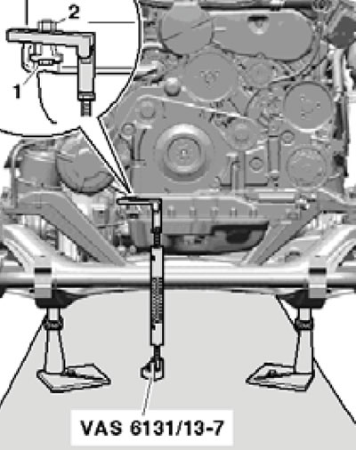
4.55. Support under the front side of the engine.
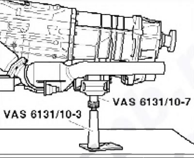
56. Install supports from sets VAS6131 /10 and -/13 under the front side of the AT pan (see illustration).
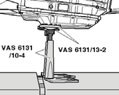
4.56. Supports under the front side of the AT pallet.
57. Install the supports from the VAS6131/10, -/12 and -/13 kits to support the front propeller shaft (see illustration).
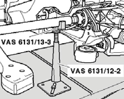
4.57. Supports under the front propeller shaft.
58. Remove the bolts on the particulate filter and primary catalytic converter brackets (see illustrations).
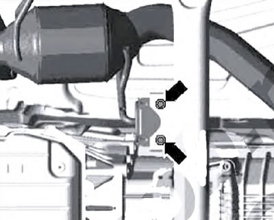
4.58a. Diesel particulate filter bracket bolts.
4.58b. Primary catalytic converter bracket bolt.
59. On BUG and BUN engines, unscrew the bolts (see illustration) and remove the turbocharger heat shield.
4.59. Turbocharger heat shield bolts (bUG/BUN engines).
Note: Bottom bolt (right arrow) turn it inside out.
60. On CASA and CASB engines, unscrew the bolts (1 in the illustration), loosen the bolt (3), move the vacuum hose with the bracket (2) to the side and remove the turbocharger heat shield bracket.
4.60. Vacuum hose fastener (cASA/CASB engines).
61. Give me the nuts (see illustration) and separate the primary catalytic converter from the diesel particulate filter.
4.61. Primary catalytic converter mounting nuts with diesel particulate filter.
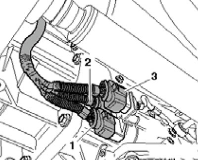
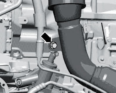
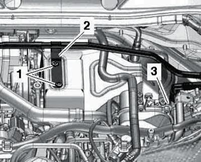
62. Disconnect the coolant hoses (1 and 2 in the illustration) on the right side of the engine.
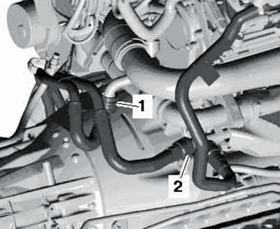
4.62. Coolant hoses on the right side of the engine.
63. Remove the bolts (1 in the illustration) and remove the coolant pipes from the rear left together with the coolant hoses.
4.63. Fastening of coolant pipes.
64. Remove the CKP sensor connector (see illustration) from the bracket and disconnect it.
4.64. SKR sensor connector.
65. Remove the front propeller shaft mounting bolts on the transfer case (see illustration).
4.65. Bolts for fastening the front propeller shaft to the transfer case.
66. Remove the bolts (1 and 2 in the illustration) and separate the ATF lines from the AT. While doing this, collect any leaking ATF with a cloth.
4.66. ATF line mounting bolts on AT.
67. Unscrew the bolt (see illustration) aTF line bracket.
4.67. ATF line bracket bolt.
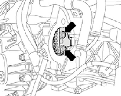
68. Loosen the drive belt tension by turning the tensioner in the direction of the arrow (see illustration) using a Torx T60 head, remove the belt and release the tensioner. If the belt is to be reinstalled, mark the direction of its movement first so that it can be installed in the same way.
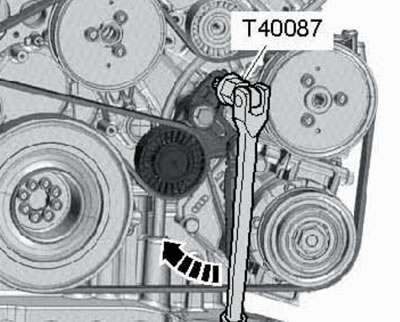
4.68. Loosening the drive belt tension.
69. Disconnect the electrical wiring from the generator (1 and 2 in the illustration) and take her aside.
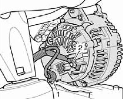
4.69. Generator wiring.
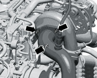
70. Remove the generator mounting bolts (see illustration) and take it off.
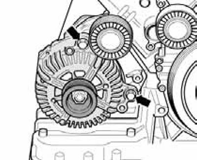
4.70. Generator fastening.
If the generator is stuck in the bracket, tighten the bolt two turns and gently hit its head with a hammer. This will release the generator support bushings.
71. Disconnect the connector (2 in the illustration) starter and disconnect the B+ wire (1) from it.
4.71. Connector (2) and connection of wire B+ (1) on the starter.
72. Unscrew the bolt (3 in the illustration) engine support bracket.
4.72. Starter bolts (1 and 2) and engine mounts (3).
Then unscrew the bolts (1 and 2) and remove the starter.
73. Insert the guide pin of the T40058 adapter with a larger diameter (2 in illustration 4.73a) outwards, and with a smaller diameter (2) - into the adapter.
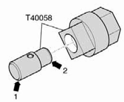
4.73a. Assembly of the T40058 device.
Hold the crankshaft from turning by installing the adapter assembled in this way on the center of the crankshaft pulley (see illustration 4.73b).
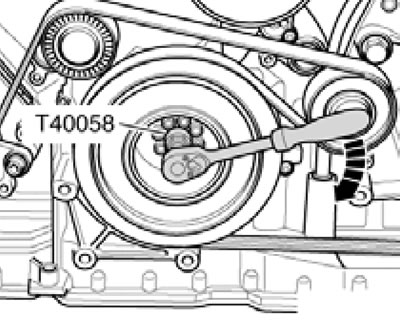
4.73b. Holding the crankshaft from turning on the pulley side.
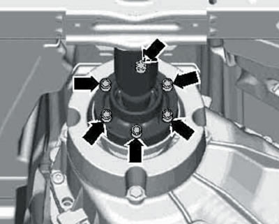
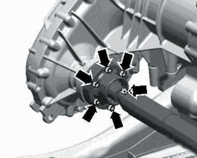
74. Mark the position of the torque converter relative to the drive disc. Then unscrew the bolts (only 6 pcs.) fastening the torque converter through the opening for the starter (see illustration), holding the crankshaft from turning by its central bolt.
4.74. Bolt for fastening the torque converter in the opening for installing the starter.
To access each subsequent pair of torque converter mounting bolts, rotate the crankshaft 120°.
75. Remove the bolts (3...10 in the illustration) aT fastenings to the engine.
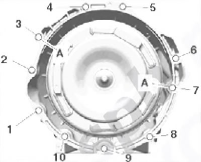
4.75. Bolts for fastening AT "09D" to the engine.
A - Centering bushings;
1, 2 - Bolt M 10x70, 45 Nm;
3...5, 7 - Bolt M 12x80, 80 Nm;
6 - Bolt M 12x70, 80 Nm;
8...10 - Bolt M10x70, 45 Nm.
76. Separate the AT from the engine by moving the coordinate table apart: the engine is supported on four supports on one part of the table, and the AT is also supported on four supports on the other part of the table. At the same time, separate the torque converter from the drive disk (see illustration).
4.76. Separating the torque converter from the drive disk.
77. Finally, secure the torque converter in the AT with tool No. 30-211A so that it does not fall out (see illustration).
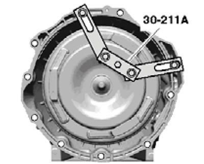
4.77. Fixing the torque converter.
78. To lift the engine from the coordinate table, use a suitable hoist hooked onto the lifting eyes (see illustration).
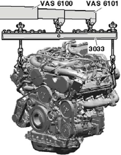
4.78. Lifting the engine.
Installation
Note: Place the hoses and wiring in the same position as they were before removal; install all clamps and ties in their original places.
79. Make sure that the AT centering bushings are present in the cylinder block; install them if necessary. In addition, the centering sleeve must be installed in the crankshaft (see illustration).
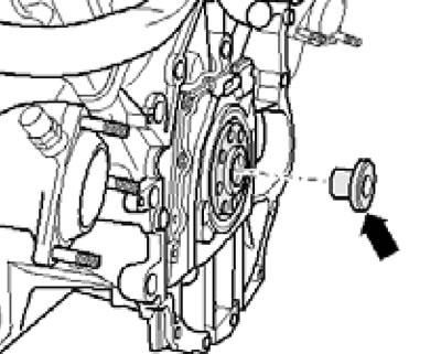
4.79. Centering sleeve in the crankshaft.
80. Install the torque converter in the AT (see Chapter 6) and make sure that it is located at a distance of approximately 22 mm from the AT flange (and in the illustration). If the torque converter is not fully installed, this distance will be approximately 10 mm.
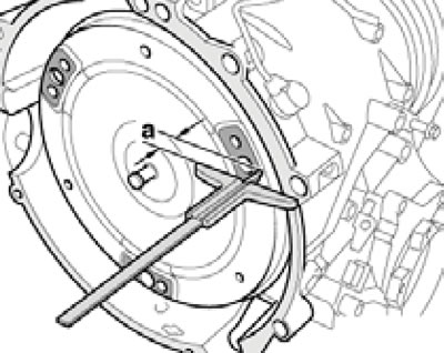
4.80. Torque converter installation depth.
81. Rotate the torque converter and drive plate so that the holes for the mounting bolts are in the opening for the starter.
82. Connect the engine to the AT and secure the torque converter to the drive disk with new knurled bolts (it is recommended to use original bolts), tightening them to 85 Nm. While tightening the bolts, hold the crankshaft from turning (see paragraph 73).
Note: Before and while tightening the torque converter mounting bolts to the engine, always ensure that the torque converter can be rotated. If the torque converter does not turn, the final tightening of the bolts will damage the drive lugs of the ATF pump and, consequently, the torque converter.
83. Further installation is carried out in reverse order. Please note the following features.
84. The tightening forces for the AT fasteners to the engine are indicated in the captions to Figure 4.75. Tighten other threaded fasteners with the following forces.
Note: Torques are given with a tolerance of ±15% for lightly lubricated, phosphated or black fasteners. Do not remove factory grease from fasteners. Additional lubrication with engine or transmission oil is permitted, but not with graphite-containing lubricants.
- Lower air pipe to radiator shroud - 9 Nm.
- Positive battery terminal stud - 15 Nm.
- Mass connection (2 in illustration 4.31) in the air intake chamber - 9 Nm.
- Mass connection (1 in illustration 4.47) on the spar - 15 Nm.
- Other fasteners M6/M8/M10/M12 - 9/20/40/65 Nm.
85. Align the subframe, engine crossmember and AT holder according to the marks made during removal. Tighten the fasteners of these parts only to the specified torque; it should be pulled to the specified angle only after adjusting the wheel alignment angles (see Chapter 9).
86. Before starting the engine for the first time, fill the power steering fluid reservoir to prevent the power steering pump from running dry. The power steering hydraulic drive and engine cooling system should be bled (see Chapters 9 and 3).
87. Finally, check the wheel alignment angles (see Chapter 9) and initialize the electric window lifter drive (see chapter "Governing bodies").