
Table of contents: 6-speed AT ↓ 8-speed AT ↓
Note: The process of removing the AT greatly depends on which engine it is installed with. However, the general procedure is the same for all models.
6-speed AT
Note: The description is given using the example of models with a 3.0 l TDI engine.
1. Remove both front wheels.
2. Remove the diesel particulate filter and catalytic converter (see Chapter 4).
3. Remove the rear left coolant pipes: on models with SCR - (see illustration 4.63 Chapter 2), and on models without SCR -(see illustration 15.31 Chapter 2).
4. Remove the air inlet hose (see illustration 4.16 Chapter 2).
5. Remove the air cleaner (see Chapter 4) and the front left wheel arch liner (see Chapter 10).
6. Follow the steps described in paragraphs 8-10 of Section 5 of Chapter 2. Partially select the motor weight by rotating the three spindles evenly.
7. Remove the rear propeller shaft and transfer case (see Chapter 7).
8. Remove the bolts (1-4 in illustration 4.53 Chapter 2) and remove the selector cable heat shield.
9. Press the hinge (2 in illustration 4.54 Chapter 2) the selector cable from the selector mechanism lever using lever No. 80-200. Then pull out the lock (1) and remove the selector cable from the AT without bending it.
10. Remove the brackets (1 in the illustration) selector cable by unscrewing the bolts (2).
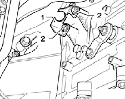
4.10. Bolts (2) of the bracket (1) of the selector cable.
11. Remove the bolts (see illustration) and remove the catalytic converter bracket.
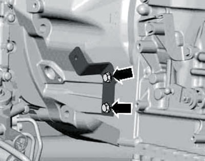
4.11. Fastening the catalytic converter bracket.
12. Remove the CKP sensor connector from the holder and disconnect it (see illustration 4.64 Chapter 2).
13. Disconnect the AT wiring connectors (1-3 in illustration 4.48 Chapter 2).
14. Remove the bolts (1 and 2 in illustration 4.66) and separate the ATF lines from the AT. Collect any leaking ATF with a cloth. Seal any open holes.
15. Remove the generator and starter (see Chapter 5).
16. If present, remove the cover from the starter mounting hole (see illustration 15.35 Chapter 2).
17. Insert the guide pin of the T40058 adapter with a larger diameter (2 in illustration 4.73a of Chapter 2) outwards, and with a smaller diameter (2) - into the adapter. Hold the crankshaft from turning by installing the adapter assembled in this way on the center of the crankshaft pulley (see illustration 4.73b in Chapter 2).
18. Mark the position of the torque converter relative to the drive disc. Then unscrew the bolts (only 6 pcs.) fastening the torque converter through the opening for the starter (see illustration 4.18 Chapter 2), holding the crankshaft from turning by its central bolt. To access each subsequent pair of torque converter mounting bolts, rotate the crankshaft 120°.
19. Remove the bolts (3-6 and 8-10 in Illustration 4.75 of Chapter 2) fastening the AT to the engine. Leave the bolt (7) screwed in by hand.
20. Slightly raise the AT on the VAG1383A transmission jack with the adapters shown in the illustration and unscrew the remaining bolt.
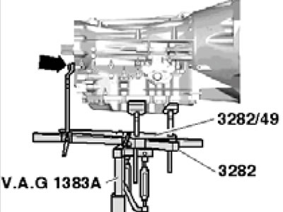
4.20. Lifting the AT with a jack.
21. Separate the AT from the engine, simultaneously separating the torque converter from the drive disc (see illustration 4.76 Chapter 2).
22. Finally, secure the torque converter in the AT with tool No. 30-211A so that it does not fall out (see illustration 4.77 Chapter 2).
23. If necessary, remove the torque converter from the AT and replace its seal. The torque converter installation details are shown in the illustration.
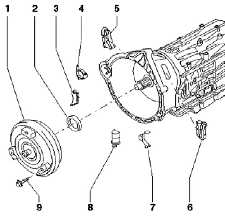
4.23. Torque converter installation details:
1 - Torque converter;
2 - Seal;
3-8 - Overlays;
9 - Bolt securing the drive disc to the torque converter, subject to replacement, 85 Nm.
24. Before installing the automatic transmission, ensure that the torque converter is properly seated in the automatic transmission. To do this, carefully slide the torque converter hub over the oil seal to the first stop and rotate the torque converter toward the automatic transmission with light force until the recess in the hub engages the pump drive and you can feel the torque converter sliding into place. If the outer lip of the torque converter seal is bent into the seal, pull the torque converter 5 mm out of the AT (so that the sponge straightens out), and then push it into the AT until it stops. The torque converter is installed correctly if it can be easily turned by hand and it is seated in the AT "09D" to a depth (And in illustration 4.80 of Chapter 2) not less than 19 mm evenly around the entire circumference.
Note: If the torque converter is not seated correctly, the torque converter drive or ATF pump will be damaged when the torque converter is attached to the engine.
25. Make sure that the support sleeve is present at the rear end of the crankshaft (see illustration 4.79 Chapter 2), and also in stock centering bushings (And in illustration 4.75 of Chapter 2) on the engine flange.
26. Before installing the reverse AT, clean the ATF pipes and ATF radiator.
27. Rotate the torque converter and drive plate so that the holes for the mounting bolts are in the opening for the starter.
28. Connect the engine to the AT and secure the torque converter to the drive disk with new knurled bolts (it is recommended to use original bolts), tightening them to 85 Nm. While tightening the bolts, hold the crankshaft from turning (see paragraph 17).
Note: Before and while tightening the torque converter mounting bolts to the engine, always ensure that the torque converter can be rotated. If the torque converter does not turn, the final tightening of the bolts will damage the drive lugs of the ATF pump and, consequently, the torque converter.
29. Further installation is carried out in reverse order. The tightening forces for the AT fasteners to the engine are indicated in the captions to Illustration 4.75 of Chapter 2. Tighten other threaded fasteners with the following forces.
Note: Torques are given with a tolerance of ±15% for lightly lubricated, phosphated or black fasteners. Do not remove factory grease from fasteners. Additional lubrication with engine or transmission oil is permitted, but not with graphite-containing lubricants.
30. After installation, check and, if necessary, adjust the levels of working fluids (see Chapter 1).
8-speed AT
Note: On 4.2L TDI models, the AT is removed together with the engine, and only then separated from it (see Chapter 2). The following description is given using the 3.0 l TDI models as an example.
31. Remove the diesel particulate filter and air cleaner housing (see Chapter 4).
32. Remove the rear and front propeller shafts (see Chapter 7).
33. Remove the coolant pipes from the AT: on the left (see illustration 25.34 Chapter 2) and top left (see illustration 25.36 Chapter 2).
34. Remove the starter (see Chapter 5) and unscrew the bolt (see illustration 4.67 Chapter 2).
35. Disconnect the AT wiring connectors (1-3 in illustration 4.48 Chapter 2).
36. Squeeze the tip (1 in illustration 15.22 Chapter 2) the selector cable from the selector mechanism lever with lever No. 80-200, unscrew the bolts (2) and remove the selector cable together with the support from the AT. Do not bend the cable.
37. Insert the guide pin of the T40058 adapter with a larger diameter (2 in illustration 4.73a of Chapter 2) outward, and with a smaller diameter (2) - into the adapter. Hold the crankshaft from turning by installing the adapter assembled in this way on the center of the crankshaft pulley (see illustration 4.73b in Chapter 2).
38. If present, remove the cover from the starter mounting hole (see illustration 25.42 Chapter 2). Mark the position of the torque converter relative to the drive disc. Then unscrew the bolts (only 6 pcs.) fastening the torque converter through the opening for the starter (see illustration 4.18 Chapter 2), holding the crankshaft from turning by its central bolt. To access each subsequent pair of torque converter mounting bolts, rotate the crankshaft 120°.
39. Remove the bolts (3-10 in illustration 15.45 Chapter 2) fastening the AT to the engine.
40. Install beam No. 10-222A with supports No. 10-222A/22 and two spindles No. 3033 located at the rear onto the flanges of the front wings (see illustration 26.8 in Chapter 2). Hook both spindles into the rear lifting eyes of the engine.
41. Install the other parts onto the support bracket as shown in the illustration.
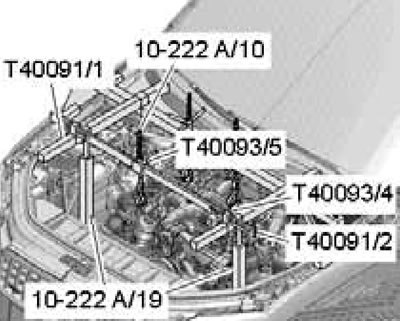
4.41. Hanging the engine.
Place adapters No. 10-222A/19 on the side member flanges. Secure all supporting elements.
42. Place the VAG1383 transmission jack with the adapter shown in the illustration under the AT and secure the AT with a clamp (1).
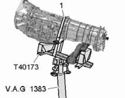
4.42. Fixing the AT on the jack.
43. Remove the bolts (1 and 2 in the illustration) aT supports and carefully lower the AT on the jack, evenly distributing the engine weight on the spindles of the lifting devices installed on top.
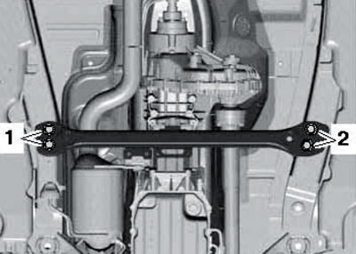
4.43. AT support fastener.
44. Remove the bolts (1-3 in illustration 23.38 Chapter 2) and separate the ATF lines from the AT, collecting the liquid with a cloth. Seal any open holes.
Note: Some models have an ATF pre-heater installed on top of the AT and the bolts (2) are not used.
45. Separate the AT from the engine, simultaneously separating the torque converter from the drive disc. Secure the torque converter in the AT with tool No. 30-211A so that it does not fall out (see illustration 4.77 Chapter 2).
46. If necessary, separate the transfer case from the AT (see Chapter 7).
47. If necessary, remove the torque converter from the AT and replace its seal. The torque converter installation details are shown in the illustration.
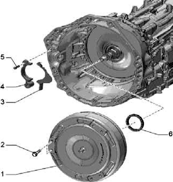
4.47. Torque converter installation details:
1 - Torque converter;
2 - Drive disc mounting bolt to torque converter, subject to replacement, 85 Nm;
3 - Overlay, there are options (depends on the engine type);
4 - Starter flange (only on 3.0L petrol models);
5 - Bolt, 10 Nm;
6 - Torque converter seal.
48. Before installing the AT, make sure. ensure the torque converter is seated correctly in the automatic transmission. To do this, carefully slide the torque converter hub over the oil seal to the first stop and rotate the torque converter toward the automatic transmission with light force until the recess in the hub engages the pump drive and you can feel the torque converter sliding into place. If the outer lip of the torque converter seal is bent into the seal, pull the torque converter 5 mm out of the AT (so that the sponge straightens out), and then push it into the torque converter until it stops. The torque converter is installed correctly if it can be easily turned by hand and it is seated in the torque converter "0C8" to a depth (And in illustration 4.80 of Chapter 2) not less than 23 mm evenly around the entire circumference.
Note: If the torque converter is not seated correctly, the torque converter drive or ATF pump will be damaged when the torque converter is attached to the engine.
49. Make sure that the centering bushings are present (And in illustration 15.45 Chapter 2) on the engine flange.
50. Before installing the reverse AT, clean the ATF pipes and ATF radiator.
51. Rotate the torque converter and drive plate so that the holes for the mounting bolts are in the opening for the starter.
52. Connect the engine to the AT and secure the torque converter to the drive disk with new knurled bolts (it is recommended to use original bolts), tightening them to 85 Nm. While tightening the bolts, hold the crankshaft from turning (see paragraph 37).
Note: Before and while tightening the torque converter mounting bolts to the engine, always ensure that the torque converter can be rotated. If the torque converter does not turn, the final tightening of the bolts will damage the drive lugs of the ATF pump and, consequently, the torque converter.
53. Further installation is carried out in reverse order. The tightening forces for the AT fasteners to the engine are indicated in the captions to illustrations 15.45 Chapter 2. Tighten other threaded fasteners to the following torques.
Note: Torques are given with a tolerance of ±15% for lightly lubricated, phosphated or black fasteners. Do not remove factory grease from fasteners. Additional lubrication with engine or transmission oil is permitted, but not with graphite-containing lubricants.
54. After installation, check and, if necessary, adjust the levels of working fluids (see Chapter 1).
(This article was copied from an online resource AUDImanual.ru)